- Community
- Documentation
- User’s Manuals, Compile Options, FAQs, Wiki
- Example Problems
- Reports and Publications
- Related software
- News
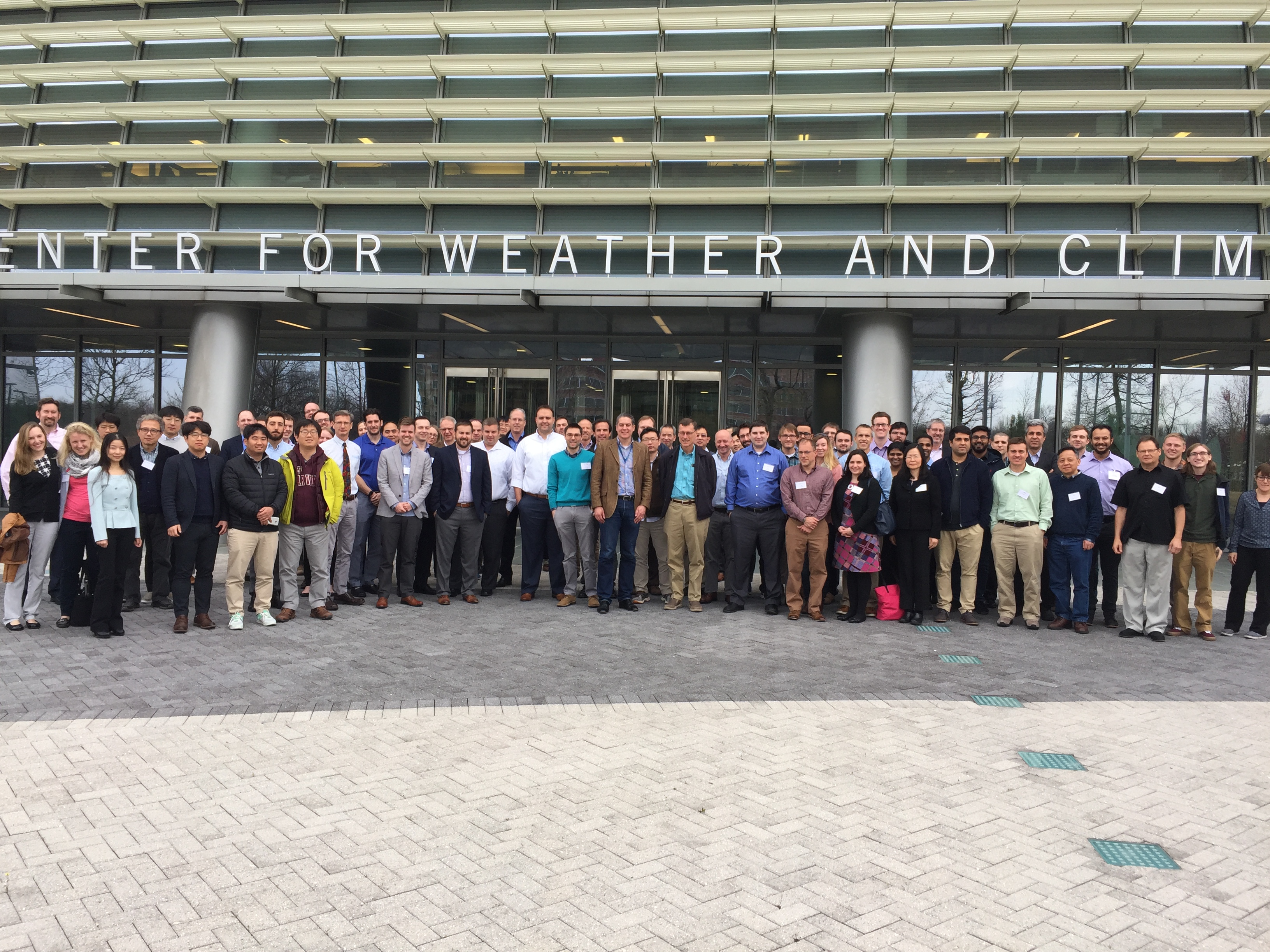
- 2020 Users Group Meeting Presentations
- 2019 ADCIRC Users Group Meeting
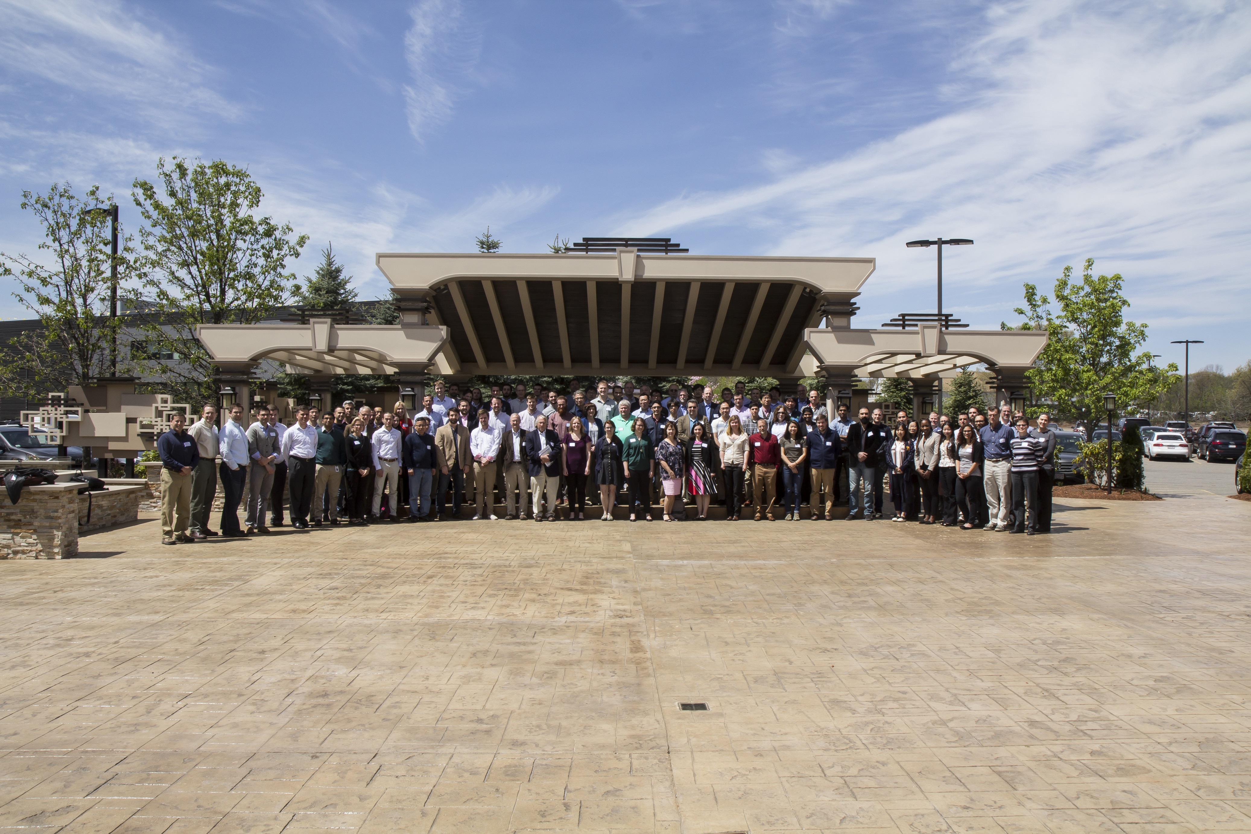
- 2019 Texas ADCIRC Week
- 2018 ADCIRC Week
- 2017 ADCIRC User Group Meeting and ADCIRC Boot Camp
- 2016 ADCIRC User’s Group Meeting and ADCIRC Boot Camp
- 2015 ADCIRC User’s Group Meeting and ADCIRC Boot Camp
- 2014 ADCIRC Workshop and Bootcamp
- ADCIRC Workshop 2013 Final Agenda
- 2011 ADCIRC Workshop Press Release
- 2010 ADCIRC Workshop Abstracts
- 2008 ADCIRC Workshop
- Hurricane Storm Surge Forecasts
- Example Hurricane Katrina Simulation
- Products
- ASGS
ADCIRC
The Official ADCIRC Web Site
Parameter Definitions
AGRID = alpha-numeric grid identification (<=24 characters).
BARINCFSB(k,j) = coefficient of free surface subcritical flow at internal barrier node NBVV(k,j) and the paired node IBCONN(k,j). A typical value is BARINCFSB(k,j) = 1.0.
BARINCFSP(k,j) = coefficient of free surface supercritical flow at internal barrier node NBVV(k,j) and the paired node IBCONN(k,j). A typical value is BARINCFSP(k,j) = 1.0.
BARINHT(k,j) = internal barrier height (positive above the geoid and negative below the geoid) at node NBVV(k,j) and the paired node IBCONN(k,j)). The barrier height must be greater than the bathymetric depth at these nodes, i.e., recalling the different sign convention between the bathymetric depth and the barrier height, BARINHT(k,j) > –DP(NBVV(k,j) and <b >BARINHT(k,j) > –DP(IBCONN(k,j)). If this is not satisfied, the run will terminate.
BARLANCFSP(k,j) = coefficient of free surface supercritical flow at external barrier node NBVV(k,j). A typical value is BARLANCFSP(k,j)= 1.0.
BARLANHT(k,j) = external barrier height (positive above the geoid and negative below the geoid) at node NBVV(k,j). The barrier height must be greater than the bathymetric depth at this node, i.e., recalling the different sign convention between the bathymetric depth and the barrier height, BARLANHT(k,j) > –DP(NBVV(k,j). If this is not satisfied, the run will terminate.
BK(k) = bridge pier shape factor (K – see Table 1 in the section on Bridge Piers)
BALPHA(k) = fraction of the cross section occupied by all of the piers in the bridge = sum of bridge pier widths/width of cross section (corresponds to
in the section on Bridge Piers)
BDELX(k) = approximate nodal spacing at the location of a bridge in the upstream/downstream direction in meters or feet depending on the grid coordinate system (for lon,lat coordinates, use meters for BDELX). (Note that 2*BDELX if the bridge pier effects are distributed across 3 nodes in the alongstream direction)
DP(JN) = bathymetric depth with respect to the geoid, positive below the geoid and negative above the geoid. Bathymetric depths above the geoid or sufficiently small that nodes will dry, require that the wetting/drying option is enabled (NOLIFA=2 in the Model Parameter and Periodic Boundary Condition File.)
IBCONN(k,j)= back face node paired with the front face node, NBVV(k,j), on an internal barrier boundary
= 0 external boundary with no normal flow as an essential boundary condition and no constraint on tangential flow. This is applied by zeroing the normal boundary flux integral in the continuity equation and by zeroing the normal velocity in the momentum equations. This boundary condition should satisfy no normal flow in a global sense and no normal flow at each boundary node. This type of boundary represents a mainland boundary with a strong no normal flow condition and free tangential slip.
= 1 internal boundary with no normal flow treated as an essential boundary condition and no constraint on the tangential flow. This is applied by zeroing the normal boundary flux integral in the continuity equation and by zeroing the normal velocity in the momentum equations. This boundary condition should satisfy no
normal flow in a global sense and no normal flow at each boundary node. This type of boundary represents an island boundary with a strong normal flow condition and free tangential slip.
= 2 external boundary with non-zero normal flow as an essential boundary condition and no constraint on the tangential flow. This is applied by specifying the non-zero contribution to the normal boundary flux integral in the continuity equation and by specifying the non-zero normal velocity in the momentum equations. This boundary condition should correctly satisfy the flux balance in a global sense and the normal flux at each boundary node. This type of boundary represents a river inflow or open ocean boundary with a strong specified normal flow condition and free tangential slip. Discharges are specified either in the Model Parameter and Periodic Boundary Condition File for harmonic discharge forcing or in the Non-periodic, Normal Flux Boundary Condition File for time series discharge forcing.
= 3 external barrier boundary with either zero or non-zero normal outflow from the domain as an essential boundary condition and no constraint on the tangential flow. This is applied by specifying the contribution (zero or non-zero) to the normal boundary flux integral in the continuity equation and by specifying the (zero or non-zero) normal velocity in the momentum equations. Non-zero normal flow is computed using a supercritical, free surface weir formula if the barrier is overtopped. Zero normal flow is assumed if the barrier is not overtopped. This boundary condition should correctly satisfy the flux balance in a global sense and the normal flux at each boundary node. This type of boundary represents a mainland boundary comprised of a dike or levee with strong specified normal flow condition and free tangential slip. See External Barrier Boundary Note below for further information on exterior barrier boundaries.
= 4 internal barrier boundary with either zero or non-zero normal flow across the barrier as an essential boundary condition and no constraint on the tangential flow. This is applied by specifying the contribution (zero or non-zero) to the normal boundary flux integral in the continuity equation and by specifying the normal velocity (zero or non-zero) in the momentum equations. Non-zero normal flow is compute using either subcritical or supercritical, free surface weir formula (based on the water level on both sides of the barrier) if the barrier is overtopped. Zero normal flow is assumed if the barrier is not overtopped. This type of boundary represents a dike or levee that lies inside the computational domain with a strong specified normal flow condition and free tangential slip. See Internal Barrier Boundary Note for further information on exterior barrier boundaries.
= 5 internal barrier boundary with additional cross barrier pipes located under the crown. Cross barrier flow is treated as an essential normal flow boundary condition which leaves/enters the domain on one side of the barrier and enters/leaves the domain on the corresponding opposite side of the barrier flow rate and direction are based on barrier height, surface water elevation on both sides of the barrier, barrier coefficient and the appropriate barrier flow formula. In addition cross barrier pipe flow rate and direction are based on pipe crown height, surface water elevation on both sides of the barrier, pipe friction coefficient, pipe diameter and the appropriate pipe flow formula. Free tangential slip is allowed
= 10 external boundary with no normal and no tangential flow as essential boundary conditions. This is applied by zeroing the normal boundary flux integral in the continuity equation and by setting the velocity = 0 rather than solving momentum equations along the boundary. This boundary condition should
satisfy no normal flow in a global sense and zero velocity at each boundary node. This type of boundary represents a mainland boundary with strong no normal flow and no tangential slip conditions.
= 11 internal boundary with no normal and no tangential flow as essential boundary conditions. This is applied by zeroing the normal boundary flux integral in the continuity equation and by setting the velocity = 0 rather than solving momentum equations along the boundary. This boundary condition should
correctly satisfy no normal flow in a global sense and zero velocity at each boundary node. This type of boundary represents an island boundary with strong no normal flow and no tangential slip conditions.
= 12 external boundary with non-zero normal and zero tangential flow as an essential boundary condition. This is applied by specifying the non-zero contribution to the normal boundary flux integral in the continuity equation and by setting the non-zero normal velocity and zero tangential velocity rather than solving momentum equations along the boundary. This boundary condition should correctly satisfy the flux balance in a global sense and the specified normal/zero tangential velocity at each boundary node. This type of boundary represents a river inflow or open ocean boundary in which strong normal flow is specified with no tangential slip. Discharges are specified either in the Model Parameter and Periodic Boundary Condition File for harmonic forcing or in the Non-periodic, Normal Flux Boundary Condition File for time series forcing.
= 13 external barrier boundary with either zero or non-zero normal outflow from the domain and zero tangential flow as essential boundary conditions. This is applied by specifying the contribution (zero or non-zero) to the normal boundary flux integral in the continuity equation and by setting the (zero or non-zero) normal velocity and zero tangential velocity rather than solving momentum equations along the boundary. Non-zero normal flow is computed using a supercritical, free surface weir formula if the barrier is overtopped. Zero normal flow is assumed if the barrier is not overtopped. This boundary condition should correctly satisfy the flux balance in a global sense and the normal velocity/zero tangential velocity at each boundary node. This type of boundary represents a mainland boundary comprised of a dike or levee with strong specified normal flow and no tangential slip conditions. See External Barrier Boundary Note below for further information on exterior barrier boundaries.
= 20 external boundary with no normal flow as a natural boundary condition and no constraint on tangential flow. This is applied by zeroing the normal boundary flux integral in the continuity equation. There is no constraint on velocity (normal or tangential) applied in the momentum equations. This boundary condition should satisfy no normal flow in a global sense, but will only satisfy no normal flow at each boundary node in the limit of infinite resolution. This type of boundary represents a mainland boundary with a weak no normal flow condition and free tangential slip.
= 21 internal boundary with no normal flow as a natural boundary condition and no constraint on the tangential flow. This is applied by zeroing the normal boundary flux integral in the continuity equation. There is no constraint on velocity (normal or tangential) in the momentum equations. This boundary condition should satisfy no normal flow in a global sense but will only satisfy no normal flow at each boundary node in the limit of infinite resolution. This type of boundary represents an island boundary with a weak no normal flow condition and free tangential slip.
= 22 external boundary with non-zero normal flow as a natural boundary condition and no constraint on the tangential flow. This is applied by specifying the non-zero contribution to the normal boundary flux integral in the continuity equation. There is no constraint on velocity (normal or tangential) in the momentum equations. This boundary condition should correctly satisfy the flux balance in a global sense but will only satisfy the normal flow at each boundary node in the limit of infinite resolution. This type of boundary represents a river inflow or open ocean boundary with a weak specified normal flow condition and free tangential slip. Discharges are specified either in the Model Parameter and Periodic Boundary Condition File for harmonic discharge forcing or in the Non-periodic, Normal Flux Boundary Condition File for time series discharge forcing.
= 23 external barrier boundary with either zero or non-zero normal outflow from the domain as a natural boundary condition and no constraint on the tangential flow. This is applied by specifying the contribution (zero or non-zero) to the normal boundary flux integral in the continuity equation. There is no
constraint on velocity (normal or tangential) in the momentum equations. Non-zero normal flow is computed using a supercritical, free surface weir formula if the barrier is overtopped. Zero normal flow is assumed if the barrier is not overtopped. This boundary condition should correctly satisfy the flux balance in a global sense but will only satisfy the normal flow at each boundary node in the limit of infinite resolution. This type of boundary represents a mainland boundary comprised of a dike or levee with a weak specified normal flow condition and free tangential slip. See External Barrier Boundary Note below for further information on exterior barrier boundaries.
= 24 internal barrier boundary with either zero or non-zero normal flow across the barrier as a natural boundary condition and no constraint on the tangential flow. This is applied by specifying the contribution (zero or non-zero) to the normal boundary flux integral in the continuity equation. There is no
constraint on velocity (normal or tangential) in the momentum equations. Non-zero normal flow is compute using either subcritical or supercritical, free surface weir formula (based on the water level on both sides of the barrier) if the barrier is overtopped. Zero normal flow is assumed if the barrier is not overtopped. This boundary condition should correctly satisfy the flux balance in a global sense but will only satisfy the normal flow at each boundary node in the limit of infinite resolution. This type of boundary represents a dike or levee that lies inside the computational domain with a weak specified normal flow condition and free tangential slip. See Internal Barrier Boundary Note below for further information on exterior barrier boundaries.
= 25 internal barrier boundary with additional cross barrier pipes located under the crown. Cross barrier flow is treated as a natural normal flow boundary condition which leaves/enters the domain on one side of the barrier and enters/leaves the domain on the corresponding opposite side of the barrier. Flow rate and direction are based on barrier height, surface water elevation on both sides of the barrier, barrier coefficient and the appropriate barrier flow formula. In addition cross barrier pipe flow rate and direction are based on pipe crown height, surface water elevation on both sides of the barrier, pipe friction coefficient, pipe diameter and the appropriate pipe flow formula. Free tangential slip is allowed.
= 30 wave radiation normal to the boundary as a natural boundary condition. This is applied by specifying the contribution to the normal boundary flux integral in the continuity equation. There is no constraint on velocity (normal or tangential) in the momentum equations. The normal flow is computed using a Sommerfield radiation condition. This boundary condition should correctly satisfy the flux balance in a global sense but will only satisfy the normal flow at each boundary node in the limit of infinite resolution. This type of boundary represents an open boundary where waves are allowed to propagate freely out of the domain.
= 32 a combined specified normal flux and outward radiating boundary. The GWCE is forced with the total normal flux computed by adding the specified normal flux and the flux associated with the outward radiating wave. The latter is determine from a Sommerfeld type condition, flux=celerity*wave elevation. The momentum equations are used to compute the velocity field the same as for a nonboundary node.
= 40 a zero normal velocity gradient boundary. The GWCE is forced with normal flux, the momentum eqs are sacrificed in favor of setting the velocity at a boundary node equal to the value at a fictitious point inside the domain. The fictitious point lies on the inward directed normal to the boundary a distance equal to the distance from the boundary node to its farthest ‘neighbor. This should ensure that the fictitious point does not fall into an element that contains the boundary node. The velocity at the fictitious point is determined by interpolation.
= 41 a zero normal velocity gradient boundary. The GWCE is forced with normal flux. The momentum eqs are sacrificed in favor of eqs that set the velocity gradient normal to the boundary equal to zero in the Galerkin sense.
= 52 external boundary with periodic non-zero normal flow combined with wave radiation normal to the boundary as natural boundary conditions and no constraint on the tangential flow. This is applied by specifying the non-zero contribution to the normal boundary flux integral in the continuity equation. There is no constraint on velocity (normal or tangential) in the momentum equations. This boundary condition should correctly satisfy the flux balance in a global sense but will only satisfy the normal flow at each boundary node in the limit of infinite resolution. This type of boundary represents a periodic river inflow or open ocean boundary with a weak specified normal flow condition and free tangential slip where waves are allowed to propagate freely out of the domain. Discharges are specified in the Model Parameter and Periodic Boundary Condition File as harmonic discharge forcing. Additional parameters, including DRampExtFlux and FluxSettlingTime must also be set in the Model Parameter and Periodic Boundary Condition File in order to use this boundary type.
= 102, 112, or 122 flux specified baroclinic. In order to designate a river boundary as baroclinic, 100 should be added to the IBTYPE that would be appropriate in the barotropic case. For example, to convert a barotropic river boundary (IBTYPE of 22) to a baroclinic river boundary with freshwater inflow, change the IBTYPE to 122. If there is a 1 in the 100s place of the IBTYPE, ADCIRC will then try to read an input file (fort.39) for the salinity and/or temperature boundary condition. The format of the fort.39 file depends on the value of IDEN; see the documentation of the fort.39 file for more details.
IBTYPEE = elevation boundary type, (At present the only allowable value for IBTYPEE is 0). Elevations are specified either in the Model Parameter and Periodic Boundary Condition File for harmonic forcing or in the Non-periodic Elevation Boundary Condition File for time series forcing.
PIPEHT(k,j) = cross barrier pipe height in internal barrier with cross barrier pipes.
PIPECOEF(k,j) = The bulk pipe friction factor for the internal barrier boundary cross-barrier pipe boundary node pair. This bulk friction factor is defined as: PIPECOEFR = fL/D where f is the classical pipe friction coefficient, L is the length of the pipe through the barrier (in consistent units) and D is the diameter of the cross barrier pipe (in consistent units).
PIPEDIAM(k,j) = cross barrier pipe diameter in internal barrier with cross barrier pipes (diameter in units consistent with the mesh).
JE = element number. The elements must be input in ascending order.
JN = node number. The nodes must be input in ascending order.
NBDV(k,j) = node numbers on elevation specified boundary segment k. The node numbers must be entered in order as one moves along the boundary segment, however the direction (counter clockwise or clockwise around the domain) does not matter.
NBPNODES = total number of nodes (centerline and adjacent) in ADCIRC grid used to represent the effects of bridge piers
NBNNUM(k) = node number in the ADCIRC grid of node k used to represent the frictional effects of bridge piers
NBOU = number of normal flow (discharge) specified boundary segments. These include zero normal flow (land) boundaries, non-zero normal flow (river) boundaries, potentially overflowing external barrier boundaries, potentially overtopping internal barrier boundaries and radiation boundaries. See also General Notes for Normal Flow Boundary Conditions.
NBVV(k,j) = node numbers on normal flow boundary segment k. The node numbers must be entered in order as one moves along the boundary segment with land always on the right, i.e., in a counter clockwise direction for external (e.g., mainland, external barrier) boundaries and a clockwise direction for internal (e.g., island, internal barrier) boundaries. For an internal barrier boundary (IBTYPE(k) = 4, 24) only the nodes on the front face of the boundary are specified in NBVV(k,j). The paired nodes on the back face of the boundary are specified in IBCONN(k,j).
NE = number of elements in the horizontal grid
NETA = total number of elevation specified boundary nodes
NHY = number of nodes per element. At present the only allowable value for the number of nodes per element is 3 indicating a triangular element with linear basis functions.
NM(JE,1), NM(JE,2), NM(JE,3) = node numbers comprising element JE. These must be specified in a counter clockwise direction moving around the element.
NOPE = number of elevation specified boundary forcing
segments.
NP = number of nodes in the horizontal grid
NVDLL(k) = number of nodes in elevation boundary segment k
NVEL = total number of normal flow specified boundary nodes including both the front and back nodes on internal barrier boundaries.
NVELL(k) = number of nodes in normal flow specified boundary segment k. For an internal barrier boundary (IBTYPE 4 or 24), NVELL(k) includes only the nodes on the front face of the boundary as specified in NBVV(k,j) and not the paired nodes on the back face of the boundary specified in IBCONN(k,j).
X(JN), Y(JN) = X and Y coordinates. If ICS=1 in the Model Parameter and Periodic Boundary Condition File then X(JN), Y(JN) are Cartesian coordinates with units of length (e.g., feet or meters) that are consistent with the definition of gravity in the Model Parameter and Periodic Boundary Condition File. If ICS=2 in the Model Parameter and Periodic Boundary Condition File then X(JN), Y(JN) are spherical coordinates in degrees of longitude (east of Greenwich is positive and west of Greenwich is negative) and degrees of latitude (north of the equator is positive and south of the equator is negative)
RUNDES = alpha-numeric run description 1 (<=32 characters)
RUNID = alphanumeric run description 2 (<= 24 characters)
NFOVER = non-fatal error override option;
= 0, inconsistent input parameters will cause program termination.
= 1, inconsistent input parameters will, (when possible), be automatically corrected to a default or consistent value and execution continued. Be sure to read the nonfatal warning messages to see whether any parameters have been modified. Note that not all inconsistent parameters can be corrected automatically and therefore fatal error messages and program termination may still result.
Note for NFOVER:
Occasionally, the elevation solution becomes unphysically large due to improper numerical parameter settings, time step stability criteria violation. It can be useful for ADCIRC to terminate based on a user-specific limit to the computed water elevation. To enable this feature, ADCIRC must be compiled with the DEBUG_WARN_ELEV compiler directive. This is set in the cmplrflags.mk file. For example, for the serial model,
DA := -DREAL8 -DLINUX -DCSCA –DDEBUG_WARN_ELEV
and for the parallel model:
DP := -DREAL8 -DLINUX -DCSCA -DCMPI -DDEBUG_WARN_ELEV
This enables extra parameters in the fort.15 file, specified on the NFOVER line:
NFOVER, WarnElev, iWarnElevDump, WarnElevDumpLimit, ErrorElev
ADCIRC then monitors the maximum water elevation and behaves as follows:
A warning is issued if the elevation exceeds WarnElev.
A global elevation file (written to fort.69) will be written if WarnElev is exceeded AND iWarnElevDump == 1
Execution will be terminated if WarnElevDumpLimit global elevation files have been written due to the above warning limits.
Execution will be terminated if elevation exceeds ErrorElev.
The default values are:
WarnElev = 20.0 ! Warn at 20 meters
iWarnElevDump = 0 ! Do not write global elevation files
WarnElevDumpLimit = 50 ! Terminate execution if the warning level is reached 50 times
ErrorElev = 1000.0 ! Terminate execution of the water elevation exceeds 1000 meters
Example: to override the defaults, recompile ADCIRC as above, and modify the NFOVER line in the fort.15 file:
1 10. 0 100 30.
This will cause ADCIRC to warn when the water elevation exceeds 10 meters, no global elevation files will be written, and ADCIRC will terminate if 100 warnings are generated OR the elevation exceeds 30 meters.
NABOUT = Logging level for output from ADCIRC to the screen or console as well as the ADCIRC log file (fort.16). ADCIRC writes log messages at 5 levels of severity: DEBUG, ECHO, INFO, WARNING, and ERROR (from lowest or least important to highest or most important). Selection of a logging level indicates that messages of that level and higher should be logged. Setting the logging level to WARNING or ERROR will reduce the size (and clutter) in the log files, but important information could be missed. ERROR messages generally result from problems that also cause the run to stop.
NABOUT=-1:: DEBUG-level log messages and higher. This may consume a lot of disk space and slow ADCIRC down, perhaps dramatically. Generally only useful for ADCIRC developers.
NABOUT=0:: ECHO-level log messages and higher. ECHO-level log messages include echo printing of most input files including the fort.13, fort.14 and fort.22 files.
NABOUT=1:: INFO-level log messages and higher. These messages inform the user about something that ADCIRC has done that is important but is not the result of a problem or issue.
NABOUT=2:: WARNING-level log messages and higher. These messages indicate a potential problem that is generally not fatal to the run.
NABOUT=3:: ERROR-level log messages only. These messages indicate a severe problem that usually causes the run to stop.
Prior to ADCIRC version 49, 0 (ECHO) and 1 (INFO) were the only available options. NABOUT originally stood for “Abbreviated Output” (to log files).
NSCREEN = Controls log message output to the screen (i.e., to standard output). Timestep logging will be written every abs(NSCREEN) timesteps. Output to the screen consists mainly of timestep logging.
NSCREEN<0:: Log messages that would normally be wrtten to the screen are written to a file called adcirc.log instead.
NSCREEN=0:: Log messages will not be written to the screen.
NSCREEN>0:: Log messages are written to the screen (a.k.a. standard out).
IHOT = parameter controlling whether the model is hot started. The hotstart facility is available for 2D and 3D runs. The hotstart file will also contain harmonic analysis data if harmonic analysis was underway, so that the harmonic analysis can be hotstarted as well.
= 0 cold start the model
= 17 hot start from ascii file fort.17
= 67 hot start model using input information in hot start file fort.67
= 68 hot start model using input information in hot start file fort.68
= 367 hot start model using input information in netCDF hot start file fort.67.nc
= 368 hot start model using input information in netCDF hot start file fort.68.nc
= 567 hot start model using input information in netCDF4 hot start file fort.67.nc
= 568 hot start model using input information in netCDF4 hot start file fort.68.nc
ICS = parameter controlling whether the model is run in spherical or Cartesian coordinates.
= 1 ADCIRC governing equations are in standard Cartesian coordinates. Coordinates in the grid file (fort.14) are assumed to have units of length that are consistent with the units of gravity (as specified below). In the unlikely case that tidal potential forcing (NTIP=1 or 2) and/or a spatially variable Coriolis coefficient (NCOR=1) are desired for this type of run, an inverse map projection (Carte Parallelo-grammatique) is used to obtain longitude and latitude values for the grid. However, we strongly recommend that if the model domain is large enough for either spatially variable Coriolis or tidal potential forcing to be considered important, the model should be run with spherical governing equations (ICS=2) using a longitude, latitude grid.
= 2 ADCIRC governing equations are in spherical coordinates transformed into Cartesian coordinates prior to discretization using a map projection (Carte Parallelo-grammatique – CPP). Coordinates in the grid file (fort.14) are in decimal degrees longitude and latitude.
= 0 Barotropic 2DDI run using New GWCE and Momentum equation formulations
= 1 Barotropic 3D run using New GWCE and velocity based Momentum equations
= 2 3D run using New GWCE and stress based Momentum equations (not fully implemented)
= 10 Barotropic 2DDI run using New GWCE and Momentum equation formulations plus passive scalar transport (not fully implemented)
= 11 Barotropic 3D run using New GWCE and velocity based Momentum equations plus passive scalar transport (not fully implemented)
= 20 Baroclinic 2DDI run using New GWCE and Momentum equation formulations (not fully implemented)
= 21 Baroclinic 3D run using New GWCE and velocity based Momentum equations
= 30 Baroclinic 2DDI run using New GWCE and Momentum equation formulations plus passive scalar transport (not fully implemented)
= 31 Baroclinic 3D run using New GWCE and velocity based Momentum equations plus passive scalar transport (not fully implemented)
= 111112 Barotropic 2DDI run using the lumped GWCE (instead of the default fully consistent GWCE). This option is needed to run ADCIRC in lumped + explicit mode, thereby bypassing the iterative solver. Explicit mode also requires specifying coefficients A00, B00, C00 (= 0, 1, 0) in this file. (see below)
= 611112 Barotropic 3D run using the lumped GWCE (instead of the default fully consistent GWCE). This option is needed to run ADCIRC in lumped + explicit mode, thereby bypassing the iterative solver. Explicit mode also requires specifying coefficients A00, B00, C00 (= 0, 1, 0) in this file. (see below)
IDEN = form of density forcing in the 2DDI or 3D run (for all Baroclinic model runs, the initial density, temperature and/or salinity field is read in from UNIT 11)
=-4 2DDI Diagnostic Baroclinic ADCIRC run with Salinity and Temperature forcing
=-3 2DDI Diagnostic Baroclinic ADCIRC run with Temperature forcing
=-2 2DDI Diagnostic Baroclinic ADCIRC run with Salinity forcing
=-1 2DDI Diagnostic Baroclinic ADCIRC run with Sigma T forcing
=0 Barotropic model run
=1 2DDI Prognostic Baroclinic ADCIRC run with Sigma T forcing
=2 2DDI Prognostic Baroclinic ADCIRC run with Salinity forcing
=3 2DDI Prognostic Baroclinic ADCIRC run with Temperature forcing
=4 2DDI Prognostic Baroclinic ADCIRC run with Salinity and Temperature forcing
NOLIBF = parameter controlling the type of bottom stress parameterization used in a 2DDI ADCIRC run. This parameter must be specified but is ignored in a 3D run. Note: In the NWP section, if the user selects quadratic_friction_coefficient_at_sea_floor, mannings_n_at_sea_floor, or chezy_friction_coefficient_at_sea_floor, then NOLIBF must be 1 (nonlinear friction formulation) since all those formulations are nonlinear. If the NOLIBF were anything other than 1, it is an error that will cause ADCIRC to stop.
= 0 linear bottom friction law. The friction coefficient (FFACTOR) is specified below.
= 1 quadratic bottom friction law. The friction coefficient (FFACTOR) is specified below.
= 2 hybrid nonlinear bottom friction law. In deep water, the friction coefficient is constant and a quadratic bottom friction law results. In shallow water the friction coefficient increases as the depth decreases (e.g. as in a
Manning-type friction law). The friction coefficient is determined as: FFACTOR=FFACTORMIN*[1+(HBREAK/H)**FTHETA]**(FGAMMA/FTHETA). The required parameters (FFACTORMIN, HBREAK, FTHETA, FGAMMA)
are specified below.
NOLIFA = parameter controlling the finite amplitude terms in ADCIRC. The value of NOLIFA effects the meaning of the minimum water depth parameter(H0) and requires the specification of additional parameters together with H0, (see below). When the finite amplitude terms are turned on, the time derivative portion of the advective terms should also be turned on for proper mass conservation and consistency (i.e. when NOLIFA>0, then NOLICAT=1).
= 0 finite amplitude terms ARE NOT included in the model run (i.e., the depth is linearized by using the bathymetric depth, rather than the total depth, in all terms except the transient term in the continuity equation)
and wetting and drying of elements is disabled. Initial water depths are assumed equal to the bathymetric water depth specified in the grid file (fort.14).
= 1 finite amplitude terms ARE included in the model run and wetting and drying of elements is disabled. Initial water depths are assumed equal to the bathymetric water depth specified in the grid file (fort.14).
= 2 finite amplitude terms ARE included in the model run and wetting and drying of elements is enabled. Initial water depths are assumed equal to the bathymetric water depth specified in the grid file (fort.14).
NOLICA = parameter controlling the advective terms in ADCIRC (with the exception of a time derivative portion that occurs in the GWCE form of the continuity equation and is controlled by NOLICAT).
When these (spatial derivative) portions of the advective terms are included, the time derivative portion of the advective terms in the GWCE should also be included (i.e. when NOLICA=1, NOLICAT=1).
= 0 advective terms ARE NOT included in the computations
= 1 advective terms ARE included in the computations
The NOLICA and NOLICAT parameters by themselves will activate or deactivate the advective terms over the full domain; however, these terms can also be activated or deactivated on an element-by-element basis. Please see the definition of the advection_state nodal attribute in the documentation for the Nodal Attributes File (fort.13) for details.
NOLICAT = parameter controlling the time derivative portion of the advective terms that occurs in the GWCE form of the continuity equation in ADCIRC. The remainder of the advective terms in the GWCE and the entire advective terms in the momentum equation are controlled by NOLICA. These terms should be included if either the finite amplitude or the remainder of the advective terms are included to maintain mass conservation and solution consistency.
= 0 the time derivative portion of the advective terms that occur in the GWCE continuity equation ARE NOT included in the computations.
= 1 the time derivative portion of the advective terms that occur in the GWCE continuity equation ARE included in the computations.
The NOLICA and NOLICAT parameters by themselves will activate or deactivate the advective terms over the full domain; however, these terms can also be activated or deactivated on an element-by-element basis. Please see the definition of the advection_state nodal attribute in the documentation for the Nodal Attributes File (fort.13) for details.
NWP = Number of nodal attributes used in the run. Nodal attributes are properties of each node in the grid and are spatially varying but constant in time. See AttrName for examples. The nodal attribute data itself must be provided by the user in the Nodal Attributes File (fort.13). If NWP is not zero, then the names of the nodal attributes appear on the following lines, one per line:
FOR j=1 to NWP
end j loop
NCOR = parameter controlling whether the Coriolis parameter is constant in space and read in below or spatially varying as computed from the y-coordinates of the nodes in the grid (assumed to be in degrees Latitude). The grid coordinate system is specified by the ICS parameter (see above).
= 0, to read in a spatially constant Coriolis parameter
= 1, to compute a spatially variable Coriolis parameter
NTIP = parameter controlling whether tidal potential and self attraction/load tide forcings will be used to
force ADCIRC.
= 0, tidal potential & self attraction/load tide forcings are not used
= 1, tidal potential forcing is used
= 2, tidal potential & self attraction/load tide forcings are used. In this case the self attraction/load tide information is read in for each constituent at each node in the grid from the Self Attraction/Earth Load Tide Forcing File.
NWS = parameter controlling whether wind velocity or stress, wave radiation stress and atmospheric pressure are used to force ADCIRC.
= 0, no wind, radiation stress or atmospheric pressure forcings are used.
= 1, wind stress and atmospheric pressure are read in at all grid nodes at every model time step from the Single File Meteorological Forcing Input File.
= 2, wind stress and atmospheric pressure are read in at all grid nodes at a time interval that does not equal the model time step from the Single File Meteorological Forcing Input File. Interpolation in time is used to synchronize the wind and pressure information with the model time step. The wind time interval (WTIMINC) is specified below.
= -2, wind stress and atmospheric pressure are read in at all grid nodes at a time interval that does not equal the model time step from the Single File Meteorological Forcing Input File. It is assumed that the first entry in the Single File Meteorological Forcing Input File corresponds to the time that the current model run is started. Specifically, if the model is hot started, it is assumed that first entry in the Single File Meteorological Forcing Input File corresponds to the model hot start time. Succeeding entries in the Single File Meteorological Forcing Input File occur at the time interval (WTIMINC) specified below. Interpolation in time is used to synchronize the wind and pressure information with the model time step.
= 3, wind velocity is read in from a wind file from the Single File Meteorological Forcing Input File in US Navy Fleet Numeric format. This information is interpolated in space onto the ADCIRC grid and in time to synchronize the wind and pressure information with the model time step. Garret’s formula is used to compute wind stress from the wind velocity. Several parameters (IREFYR, IREFMO, IREFDAY, IREFHR, IREFMIN,
REFSEC, NWLAT, NWLON, WLATMAX, WLONMIN, WLATINC, WLONINC, WTIMINC) describing the Fleet Numeric wind file must be specified below.
= 4, wind velocity and atmospheric pressure are read in (PBL/JAG format) at selected ADCIRC grid nodes from the Single File Meteorological Forcing Input File. It is assumed that the first entry in the Single File Meteorological Forcing Input File corresponds to the beginning of the model run (e.g., the cold start time). Succeeding entries occur at the time interval (WTIMINC) specified below. Thus, if the model is hot started wind data must exist in the fort.22 file dating back to the beginning of the model run so that the model can find its appropriate place in the file. Interpolation in time is used to synchronize the wind and pressure information with the model time step. Garret’s formula is used to compute wind stress from wind velocity.
=-4, wind velocity and atmospheric pressure are read in (PBL/JAG format) at selected ADCIRC grid nodes from the Single File Meteorological Forcing Input File. It is assumed that the first entry in the Single File Meteorological Forcing Input File corresponds to the time that the current model run is started. Specifically, if the model is hot started, it is assumed that first entry in the Single File Meteorological Forcing Input File corresponds to the model hot start time. Succeeding entries in the Single File Meteorological Forcing Input File occur at the time interval (WTIMINC) specified below. Interpolation in time is used to synchronize the wind and pressure information with the model time step. Garret’s formula is used to compute wind stress from wind velocity.
= 5, wind velocity and atmospheric pressure are read in at all grid nodes from the Single File Meteorological Forcing Input File. It is assumed that the first entry in the Single File Meteorological Forcing Input File corresponds to the beginning of the model run (e.g., the cold start time). Succeeding entries occur at the time interval (WTIMINC) specified below. Thus, if the model is hot started wind data must exist in the Single File Meteorological Forcing Input File dating back to the beginning of the model run so that the model can find its appropriate place in the file. Interpolation in time is used to synchronize the wind and pressure information
with the model time step. Garret’s formula is used to compute wind stress from
wind velocity.
=-5, wind velocity and atmospheric pressure are read in at all grid nodes from the Single File Meteorological Forcing Input File. It is assumed that the first entry in the Single File Meteorological Forcing Input File corresponds to the time that the current model run is started. Specifically, if the model is hot started, it is assumed that first entry in the fort.22 file corresponds to the model hot start time. Succeeding entries in the Single File Meteorological Forcing Input File occur at the time interval (WTIMINC) specified below. Interpolation in time is used to synchronize the wind and pressure information with the model time step. Garret’s formula is used to compute wind stress from wind velocity.
= 6, wind velocity and atmospheric pressure are read in for a rectangular grid (either in Longitude, Latitude or Cartesian coordinates, consistent with the grid coordinates) from the Single File Meteorological Forcing Input File. This information is interpolated in space onto the ADCIRC grid and in time to synchronize the wind and pressure information with the model time step. Garret’s formula is used to compute wind stress from the wind velocity. Several parameters describing the rectangular grid and time increment (NWLAT, NWLON, WLATMAX, WLONMIN, WLATINC, WLONINC, WTIMINC) must be specified below. The meterological grid MUST cover the entire ADCIRC mesh; that is, the ADCIRC mesh must be ENTIRELY within the meteorological grid or an error will result.
= 7, surface stress and pressure values are read in on a regular grid from the Single File Meteorological Forcing Input File. It is assumed that the first entry in the Single File Meteorological Forcing Input File corresponds to the beginning of the model run (e.g., the cold start time). Succeeding entries occur at the time interval (WTIMINC) specified below. Thus, if the model is hot started wind data must exist in the Single File Meteorological Forcing Input File dating back to the beginning of the model run so that the model can find its appropriate place in the file. Interpolation in time is used to synchronize the wind and pressure information with the model time step.
=-7, surface stress and pressure values are read in on a regular grid from the Single File Meteorological Forcing Input File. It is assumed that the first entry in the Single File Meteorological Forcing Input File corresponds to the time that the current model run is started. Specifically, if the model is hot started, it is assumed that first entry in the fort.22 file corresponds to the model hot start time. Succeeding entries in the Single File Meteorological Forcing Input File occur at the time interval (WTIMINC) specified below. Interpolation in time is used to synchronize the wind and pressure information with the model time step.
= 8, hurricane parameters are read in from the Single File Meteorological Forcing Input File. Wind velocity and atmospheric pressure are calculated at every node on the fly by ADCIRC internally using the Dynamic Holland model. The input file is assumed to correspond to the ATCF Best Track/Objective Aid/Wind Radii Format. Historical tracks, real-time hindcast tracks and real-time forecast tracks may be found in this format. Selecting NWS = 8 also requires the specification of the cold start time, storm number, and boundary layer adjustment (see YYYY MM DD HH24 StormNumber BLAdj below). Garret’s formula is used to compute wind stress from the wind velocity.
= 9, asymmetric hurricane model, no longer supported
=10, wind velocity (10 m) and atmospheric pressure are read in from a sequence of National Weather Service (NWS) Aviation (AVN) model output files. Each AVN file is assumed to contain data on a Gaussian longitude, latitude grid at a single time. Consecutive files in the sequence are separated by N hours in time (where N=WTIMINC/3600 and WTIMINC is read in below). The files are named using the convention: fort.200 – wind & pressure at the time of a model hot start (this file is not used for a cold start); fort.XX1 (where XX1=200+1*N) – wind & pressure N hours after a cold or hot start; fort.XX2 (where XX2=200+2*N) – wind & pressure 2N hours after a cold or hot start; fort.XX3 (where XX3=200+3*N) – wind & pressure 3N hours after a cold or hot start and so on for all meteorological files. Prior to ADCIRC version 34.05 these files were in binary and created from a larger Grib form file using the program UNPKGRB1. Starting with ADCIRC version 34.05, the files are in ASCII tabular format. If ADCIRC is hot started, it must be done at an even N hour interval so that the hot start time corresponds to the time of a meteorological file. Enough meteorological files must be present to extend through the ending time of the model run. Garret’s formula is used to compute wind stress from the wind velocity.
=11, wind velocity (10 m) and atmospheric pressure are read in from a sequence of stripped down National Weather Service (NWS) ETA 29km model output files. Each ETA file is assumed to contain data on an E grid for a single day (8 data sets, one every 3 hours, beginning @ 03:00 and continuing through 24:00 of the given day). The files are named using the convention: fort.200 – wind & pressure the day before a model run is hot started. The final data in this file are used as the initial met condition for the hot start. This file is not used for a cold start. fort.201 – wind & pressure during the first day after a cold or hot start. fort.202 – wind & pressure during the second day after a cold or hot start fort.203 – wind & pressure during the third day after a cold or hot start. This sequence continues for all meteorological files. These files are in binary and have the format described below. The wind data is converted to an east-west, north-south coordinate system inside ADCIRC. If the model is hot started, it must be done at an even day interval so that the hot start time corresponds to the time of a meteorological file. Enough meteorological files must be present to extend through the ending time of the model run. Garret’s formula is used to compute wind stress from the wind velocity.
=12, wind velocity (10 minute averaged winds at 10m) and atmospheric pressure are provided in the OWI format on one or two rectangular (lat/lon) grid(s). If two grids are used, the first is designated as the large (“basin”) scale grid, and the second is designated as the small (“region”) scale grid. The Single File Meteorological Forcing Input File (fort.22) is only used to specify a few configuration parameters, while the actual wind fields are recorded in files named fort.221, fort.222, fort.223, and fort.224 (with fort.223 and fort.224 being optional). The time increment of the meteorological forcing is specified through WTIMINC in the fort.15 file. The wind and pressure fields are interpolated in space onto the ADCIRC grid and in time to synchronize the wind and pressure information with the model time step. Garret’s formula is used to compute wind stress from wind velocity.
=15, HWind files are data assimilated snapshots of the wind velocity fields of tropical cyclones that are produced by the NOAA Hurricane Research Division (HRD).
=19, User has the ability to select which Isotach to use in each of the 4 quadrants. User also has ability to modify RMAX and Holland’s B parameter using the ASWIP program. The auxiliary preprocessing program ASWIP.F (located in the /wind directory and executable is created by typing, make aswip, in the work folder after adcirc executable has been generated), will generate the fort.22 input file for NWS=19 from a NWS= 9 formatted input file.
Hurricane parameters are read in from the Single File Meteorological Forcing Input File. It is assumed that the first entry in the Single File Meteorological Forcing Input File corresponds to the beginning of the model run (e.g., the cold start time). Wind velocity and atmospheric pressure are calculated at exact finite element mesh node locations and directly coupled to ADCIRC at every time step using the asymmetric hurricane vortex formulation (Mattocks et al, 2006; Mattocks and Forbes, 2008) based on the Holland gradient wind model. The input file is assumed to correspond to the ATCF Best Track/Objective Aid/Wind Radii Format. Historical tracks, real-time hindcast tracks and real-time forecast tracks may be found in this format. This option uses the radii at specific wind speeds (34, 50, 64, 100 knots) reported in the four quadrants (NE, SE, SW, NW) of the storm to calculate the radius of maximum winds as a function of the azimuthal angle. Garret’s formula is used to compute wind stress from the wind velocity. The NWS=19 option allows the user to set a value for Rmax and Holland B Parameter. Additionally the user can select the isotachs to be used for each of the 4 quadrants. The utility program aswip_1.0.3.F located in the /wind folder will generate the NWS=19 fomatted file from a NWS=9 formatted fort.22 input file.
In order to use the NWS=19 option, the file needs to be in best track format. The forecast period (column #6) needs to be edited to reflect the time of the forecast/nowcast for each track location (each line) in hours from the start of the simulation (0, 6, 12, 18, etc). The original data in that column depends on what type of best track format data is being used. The original data might have 0 or other numbers in that column. See: http://www.nrlmry.navy.mil/atcf_web/docs/database/new/abrdeck.html
It is suggested that users change the “BEST” tech type to “ASYM” in column 5 in the fort.22 file to denote that the file has been modified to accommodate the asymmetric wind formulation (the simulation time in hours in the 6th column has been added, etc.) so it will not get confused in the future with a best track file.
The NWS=19 option requires the following variables in the fort.22 file in a best track format:
o 1) Forecast time in hours (column 6); enter the time in hours in each record starting at 0
o 2) Latitude of the eye (column 7)
o 3) Longitude of the eye (column 8)
o 4) Maximum sustained wind speed in knots (column 9)
o 5) Minimum sea level pressure in MB (column 10)
o 6) Wind intensity in knots of the radii defined in the record (34, 50, 64 or 100 knots) (column 12)
o 7) Radius of specified wind intensity for quadrants 1, 2, 3, 4 in NM (columns 14, 15, 16, 17); ? 0
o 8) Background pressure in MB (column 18); a standard value of 1013 can be used
o 9) Rmax as reported in the ATCF BEST TRACK file in column 20
o 10) Storm Name in Column 28 ATCF file format
o 11) Time Record number in column 29. There can be multiple lines for a given time record depending on the number of isotachs reported in the ATCF File
o 12) number of isotachs reported in the ATCF file for the corresponding Time record.
o 13) Columns 31-34 indicate the selection of radii for that particular isotach. 0 indicates do not use this radius, and 1 indicates use this radius and corresponding wind speed.
o 14) Columns 35-38 are the designated Rmax values computed for each of the quadrants selected for each particular isotach.
o 15) Column 39 is the Holland B parameter computed using the formulas outlines in the Holland paper, and implemented using the aswip program.
The format of the file is fixed and users will want to use the aswip program to be sure that the input fort.22 file is properly formatted.
=100, 101, 102, -102, 103, 104, -104, 105, -105, 106, 110, 111, wave radiation stress is applied in addition to meteorological forcing. The meteorological input is specified by: SIGN(NWS)*(ABS(NWS)-100). For example, NWS=100 means include wave radiation stress with no meteorological forcing (NWS=0); NWS=101 means include wave radiation stress plus meteorological
forcing corresponding to NWS=1; NWS=-104 means include wave radiation stress plus meteorological forcing corresponding to NWS=-4, etc. Wave radiation stress is read from a Wave Radiation Stress Forcing File. The format of this file is similar to the generic meteorological forcing file when NWS=-4 with the exception that no pressure values are read in. The time increment between consecutive radiation stress fields (RSTIMINC) is specified below.
=300,301,302, -302, 303, 304, -304, 305, -305, 306, 310, 311, 312, -312, NWS values in the 300’s indicate a SWAN+ADCIRC run Note padcswan or adcswan must be precompiled to use this option.
The SWAN wave model is dynamically coupled to the ADCIRC model. Radiation stresses and currents from the SWAN model are applied in addition to meteorological forcing. The meteorological input is specified by: SIGN(NWS)*(ABS(NWS)-300). For example, NWS=300 means include wave radiation stress with no meteorological forcing (NWS=0); NWS=301 means include wave radiation stress plus meteorological forcing corresponding to NWS=1; NWS=-304 means include wave radiation stress plus meteorological forcing corresponding to NWS=-4, etc. Wave radiation stress are computed by the SWAN model every RSTIMINC seconds and passed into ADCIRC. In addition to assigning RSTIMINC the user must have a SWAN input and control file (fort.26) in the same working directory as the fort.15 ADCIRC control file.
NRAMP = ramp option parameter controlling whether a ramp is applied to ADCIRC forcing functions.
= 0 no ramp function is used with forcing functions
= 1 a hyperbolic tangent ramp function is specified and applied to forcing from surface elevation specified boundary conditions, nonzero flux boundary conditions, tidal potential, wind and atmospheric pressure and wave radiation stress. See description of DRAMP for further information on the ramp function.
= 2 a hyperbolic tangent ramp function is specified and applied to forcing from surface elevation specified boundary conditions, tidal potential, wind and atmospheric pressure and wave radiation stress. A separate hyperbolic tangent ramp function is specified and applied to the nonzero external flux boundary conditions. See description of DRAMP for further information
on the ramp function.
= 3 a hyperbolic tangent ramp function is specified and applied to forcing from tidal potential, wind and atmospheric pressure and wave radiation stress. Two additional hyperbolic tangent ramp functions are specified and applied to the nonzero external flux boundary conditions and the nonzero internal flux boundary conditions. See description of DRAMP for further information
on the ramp function.
= 4 a hyperbolic tangent ramp function is specified and applied to forcing from tidal potential, wind and atmospheric pressure and wave radiation stress. Two additional hyperbolic tangent ramp functions are specified and applied to the nonzero external flux boundary conditions, the nonzero internal flux boundary conditions and the surface elevation specified boundary conditions. See description of DRAMP for further information on the ramp function.
= 5 a hyperbolic tangent ramp function is specified and applied to forcing from wind and atmospheric pressure and wave radiation
stress. Four additional hyperbolic tangent ramp functions are specified and applied to the nonzero external flux boundary
conditions and the nonzero internal flux boundary conditions, the surface elevation specified boundary conditions and to the tidal potential. See description of DRAMP for further information on the ramp function.
= 6 a hyperbolic tangent ramp function is specified and applied to forcing from wave radiation stress. Five additional hyperbolic tangent ramp functions are specified and applied to the nonzero external flux boundary conditions, the nonzero internal flux boundary conditions, the surface elevation specified boundary conditions, to the tidal potential and the wind and atmospheric pressure. See description of DRAMP for further information on the ramp function.
= 7 a general hyperbolic tangent ramp function is specified, and six additional hyperbolic tangent ramp functions are specified and applied to the nonzero external flux boundary conditions, the nonzero internal flux boundary conditions, the surface elevation specified boundary conditions, to the tidal potential, the wind and atmospheric pressure, and the wave radiation stress. See description of DRAMP for further information on the ramp function.
= 8 a general hyperbolic tangent ramp function is specified, and seven additional hyperbolic tangent ramp functions are specified and applied to the nonzero external flux boundary conditions, the nonzero internal flux boundary conditions, the surface elevation specified boundary conditions, to the tidal potential, the wind and atmospheric pressure, the wave radiation stress, and the meteorological ramp delay. The meteorological ramp delay is useful in cases where a meteorologically-forced run will be hotstarted from a meteorologically-free tidal spinup (for example). The meteorological ramp delay parameter (DUnRampMete) has the same units as DRampMete (days) and simply delays the application of the meteorological ramp for the specified length of time, relative to the ADCIRC cold start time. See description of DRAMP for further information on the ramp function.
G = gravitational constant. The units of this constant determine the distance units that ADCIRC operates with. (ADCIRC always operates in seconds and therefore the time units for G must be seconds.) When ICS = 2, it is required that G = 9.81 m/sec2. Regardless of ICS, when either NTIP = 1 or NCOR = 1, it is required that G = 9.81 m/sec2.
TAU0 = = Generalized Wave-Continuity Equation (GWCE) weighting factor that weights the relative contribution of the primitive and wave portions of the GWCE. If “primitive_weighting_in_continuity_equation” is specified as a nodal attribute in the fort.15 file above, this line will be read in but ignored. If a nodal attribute file is not used or “primitive_weighting_in_continuity_equation” is in the nodal attribute (fort.13) file, but not specified in the fort.15 file this TAU0 parameter will be used.
= 0, the GWCE is a pure wave equation.
< 1, the GWCE behaves like a pure primitive continuity equation. A good rule of thumb for setting TAU0 is to set it equal to the largest value of an equivalent linear friction factor (e.g, for linear friction TAU0 = TAU; for quadratic friction TAU0 = maximum (speed*CF/depth). Typical values for TAU0 are in the range of 0.005 – 0.1.
= -1, the TAU0 is spatially varying but constant in time; it is calculated according to depth as follows: If the depth is >=10 TAU0 is set to 0.005, if the depth is < 10, TAU0 is set to 0.020.
= -2, the TAU0 is spatially varying but constant in time; it is calculated according to depth as follows: if the depth is >=200 TAU0 is set to 0.005, if the depth is < 200 but > 1, then TAU0 is set to 1/depth, and if depth < 1, TAU0 is set to 1.0.
= -3, the TAU0 varies spatially and in time. TAU0 is computed from TAU0Base read in from nodal attribute file.
if TAU0Base < 0.025; TAU0 = TAU0Base (constant in time)
if TAU0Base >= 0.025; TAU0 = TAU0Base + 1.5 TK(i) where TK(i)=Cd|U|/H
TAU0Base values can be generated with the ADCIRC utitlity program tau0_gen.f. The program bases generation on the following logic:
If the avg. distance between a node and its neighbors < 1750 m TAU0Base = 0.03
If the avg. distance between a node and its neighbors > 1750 m AND depth < 10m; TAU0Base = 0.02
If the avg. distance between a node and its neighbors > 1750 m AND depth > 10m; TAU0Base = 0.005
= -4, the TAU0 is calculated in the same way as TAU0=-3; in this case it is also written out to a fort.tau0 file in the same format and with the same timing as the fort.63 file.
= -5, FullDomainTimeVaryingTau0 = .True. the TAU0 varies spatially and in time, and is dependent on the local friction; it is limited to a range specified by Tau0FullDomainMin and Tau0FullDomainMax.
Tau0=Tau0Min+1.5*TK(i)
Tau0FullDomainMin, Tau0FullDomainMax – include this line only if TAU0= -5 – specified values that the spatially and time varying TAU0 scheme must stay between. Suggested values are Tau0FullDomainMin = 0.005 and Tau0FullDomainMax = 0.2.
DTDP = ADCIRC time step (in seconds). Note: time in the model is computed as: TIME = STATIM*86400.+DTDP*IT.
> 0 = The predictor-corrector algorithm is not used.
< 0 = The predictor-corrector algorithm is used.
STATIM = starting simulation time (in days). The first time step computes results at: TIME = STATIM*86400+DTDP. A nonzero value may be useful, for example, to align model output times with a specific time reference.
REFTIM = reference time (in days). This is used only to compute time for the harmonic forcing and analysis terms. A nonzero value allows equilibrium arguments to be used that have been calculated for a time other than TIME0 = STATIM*86400. The time used for
harmonic terms is compute as: TIMEH = (STATIM–REFTIM)*86400.+DTDP*IT.
POAN(k)= parameter that weights bridge pier drag between adjacent and centerline nodes.
= 2 if node represents a centerline node
= 1 if node represents an adjacent node
WTIMINC = meteorological wind time interval
IF NWS = 1, 101, ADCIRC assumes WTIMINC = DTDP (model time step), no WTIMINC line is needed in the Model Parameter and Periodic Boundary Condition File.
IF NWS = 2, -2, 3, 4, -4, 5, -5, 6, 7, -7, 102, 103, 104, -104, 105, -105, 106, 107, -107, 302, 303, 304, 305, 306, 307, 402, 403, 404, 405, 406, 407, 408, 12002, 12003, 12004, 12005, 12006, 12007, 12102, 12103, 12104, 12105, 12106, 12107, 12302, 12303, 12304, 12305, 12306, 12307, 12402, 12403, 12404, 12405, 12406, 12407 WTIMINC must be specified in the Model Parameter and Periodic Boundary Condition File and is the time interval (in seconds) between successive wind and pressure data in the Single File Meteorological Forcing Input File.
IF NWS = 10, 110, 310, 410, 12010, 12110, 12310, 12410 WTIMINC must be specified in the Model Parameter and Periodic Boundary Condition File and is the time interval (in seconds) between the Multiple File Meteorological Forcing Input Files.
IF NWS = 11, 111, 311, 411,12011, 12111, 12311,12411, ADCIRC assumes WTIMINC = 10800 (3 hrs) is the time interval between the Multiple File Meteorological Forcing Input Files. , No WTIMINC line is needed in the Model Parameter and Periodic Boundary Condition File.
IF NWS = 12, 112,312,412,12012,12112,12312,12412 WTIMINC must be specified in the Model Parameter and Periodic Boundary Condition File and is the time step of the two gridded meteorological data fields. As a result, ADCIRC requires that this time step be of a constant size and that all the OWI meteorological data fields be synchronized to it.
IF NWS = 15, 115,
YYYY,MM,DD,HH24,StormNumber,BLAdj = for the Dynamic Holland model (NWS=8) and the Dynamic Asymetric Model (NWS=19), this is the coldstart datetime, the number of the storm in forecast ensemble, and the boundary layer adjustment factor. The datetime tells ADCIRC what time corresponds to t=0. For example, if the datetime is specified as 2005 08 29 06 on a cold start, then ADCIRC will find that time in the Single File Meteorological Forcing Input File, linearly interpolating if necessary, to get its initial wind state. For a hotstart, the time in the hotstart file will be added to this datetime before seeking the proper place in the Single File Meteorological Forcing Input File. For example, if the coldstart datetime is still specified as 2005 08 29 06, and the time in the hotstart file is 86400 seconds, ADCIRC will start up and interpolate in the Single File Meteorological Forcing Input File for the conditions at 6:00 am on August 30, 2005 to get its hotstart wind state. One limitation is that an ADCIRC run cannot cross the boundary of the calendar year, i.e. start in December and end in January. StormNumber is an integer and should be set to 1. BLAdj is the adjustment factor between wind speed at 10m and the wind speed at the top of the atmospheric boundary layer (winds at top of atm. b.l.)=(winds at 10m)/BLAdj. Reasonable range is 0.7 to 0.9.
RSTIMINC = time interval (in seconds) between successive wave radiation stress values in the Wave Radiation Stress Forcing File. This value must be specified in the Model Parameter and Periodic Boundary Condition File if the absolute value of NWS >=100.
IREFYR, IREFMO, IREFDAY, IREFHR, IREFMIN, REFSEC = starting time parameters for a Single File Meteorological Forcing Input File in US Navy Fleet Numeric format (NWS = 3, 103). These values are used in ADCIRC to compute WREFTIM which is the start time of the simulation in seconds since the beginning of the calendar year. ADCIRC is configured to accept only 1 calendar year’s data, i.e., it is not possible to combine Fleet Numeric met data from two different years into a single file and then run.
IREFYR = year of the start of the simulation
IREFMO = month of the start of the simulation
IREFDAY = day of the start of the simulation
IREFHR = hour of the start of the simulation
IREFMIN = minute of the start of the simulation
REFSEC = second of the start of the simulation.
NWLAT, NWLON, WLATMAX, WLONMIN, WLATINC, WLONINC = parameters describing the spatial structure of a Single File Meteorological Forcing Input File where met data is set up on a simple rectangular grid (NWS = 3, 6, 103, 106).
NWLAT = number of latitude values in the met file.
NWLON = number of longitude values in met file.
WLATMAX = maximum latitude (decimal deg) of data in met file (< 0 south of the equator).
WLONMIN = minimum longitude (decimal deg) of data in the met file (< 0 west of Greenwich meridian).
WLATINC = latitude increment (decimal deg) of data in the met file (must be > 0).
WLONINC = longitude increment (decimal deg) of data in the met file (must be > 0).
RNDAY = length of the ADCIRC run (in decimal days)
DRAMP = value (in decimal days) used to compute the ramp function that ramps up ADCIRC forcings from zero (if NRAMP=1). The ramp function is computed as RAMP=tanh(2.0*IT*DTDP/(86400.*DRAMP)) where IT = the time step number since the beginning of the model run. DRAMP is equal to the number of days when RAMP=0.96.
DRAMPExtFlux = value (in decimal days) used to compute the ramp function that ramps up the nonzero external flux boundary condition.
FluxSettlingTime = time in days that it takes for the river flux boundary condition and the river bottom friction to equilibrate so the water surface elevation can find its steady state.
Notes:
From the start of the simulation until FluxSettlingTime has passed, the only forcing that is active is the external boundary flux forcing. All other forcings are set to zero.
Once the FluxSettlingTime has passed, the other forcing functions begin their ramp up.
The new IBTYPE=52 only works with periodic flux boundary conditions. Non-periodic flux boundary conditions cannot be specified for IBTYPE=52 boundaries.
DRAMPIntFlux = value (in decimal days) used to compute the ramp function that ramps up the nonzero internal flux boundary condition.
DRAMPElev = value (in decimal days) used to compute the ramp function that ramps up the elevation-specified boundary condition.
DRAMPTip = value (in decimal days) used to compute the ramp function that ramps up the tidal potential.
DRAMPMete = value (in decimal days) used to compute the ramp function that ramps up the wind and atmospheric pressure.
DRAMPWRad = value (in decimal days) used to compute the ramp function that ramps up the wave radiation stress.
DRAMPUnMete =The meteorological ramp delay parameter with units of decimal days. It simply delays the application of the meteorological ramp for the specified length of time, relative to the ADCIRC cold start time.
A00, B00,C00 = time weighting factors (at time levels k+1, k, k-1, respectively) in the GWCE
IF NOLIFA = 0, 1, H0 = minimum bathymetric depth. All bathymetric depths in the Grid and Boundary Information File less than H0 are changed to be equal to H0.
If NOLIFA = 2, H0 = nominal water depth for a node (and the accompanying elements) to be considered dry (typical value 0.01 – 0.1 m).
INTEGER = In the past, the wetting and drying algorithm required two additional integers as input. These extra parameters are no longer needed by the code, but they are still present to maintain backward compatibility. Their values will be ignored.
VELMIN = minimum velocity for wetting. A dry node wets if a water surface slope exists that would drive water from a currently wet node to the dry node and the steady-state current velocity that resulted would have a velocity > VELMIN. This parameter helps to keep nodes/elements from repeatedly turning on and off during the
wetting process. A typical value might be 0.05 m/s.
SLAM0,SFEA0 = longitude and latitude on which the CPP coordinate projection is centered (in degrees) if ICS = 2.
TAU – bottom friction is a linear function of depth-averaged velocity and TAU is the corresponding linear friction coefficient (units of 1/sec). In this case it is strongly recommended that TAU0 = TAU (Used with NOLIBF = 0). If some type of spatially varying bottom friction is specified in the NWP section, this input is ignored, and the friction coefficients will be read in from the nodal attributes file.
CF = 2DDI bottom friction coefficient used in ADCIRC unless spatially varying bottom friction is specified using nodal attributes. If
Manning’s n is the spatially variable friction coefficient, then CF will be used as the floor on the equivalent quadratic friction coefficient
(see the documentation on the Manning’s n nodal attribute for the formula used to convert Manning’s n to an equivalent quadratic friction coefficient). If some other type of spatially varying bottom friction is specified in the NWP section, then CF is ignored entirely.
If NOLIBF = 1, bottom friction is a quadratic function of depth-averaged velocity and FFACTOR is the corresponding quadratic
friction coefficient (dimensionless).
If NOLIBF = 2, minimum friction coefficient (dimensionless) in the hybrid bottom friction relationship. This friction coefficient is
approached in deep water (H > HBREAK) where the hybrid friction relationship reverts to a quadratic function of depth-averaged
velocity.
HBREAK = the break depth (units of length) utilized for NOLIBF = 2 in the hybrid bottom friction relationship FFACTOR = FFACTORMIN*[1+(HBREAK/H)**FTHETA]**(FGAMMA/FTHETA). If the water depth (H) is greater than HBREAK, bottom friction approaches a quadratic function of depth-averaged velocity with FFACTOR = FFACTORMIN. If the water depth is less than HBREAK, the friction factor increases as the depth decreases (e.g. like a manning type friction law). (HBREAK = 1 m is recommended). If some type of spatially varying bottom friction is specified in the NWP section, this input is ignored, and the friction coefficients will be read in from the nodal attributes file.
FTHETA = a parameter (dimensionless) that determines (for NOLIBF = 2) how rapidly the hybrid bottom friction relationship approaches its deep water and shallow water limits when the water depth is greater than or less than HBREAK. (FTHETA = 10 is recommended). If some type of spatially varying bottom friction is specified in the NWP section, this input is ignored, and the friction coefficients will be read in from the nodal attributes file.
FGAMMA = a parameter (dimensionless) that determines (for NOLIBF = 2) how the friction factor increases as the water depth decreases. Setting this to 1/3 gives a manning friction law type of behavior (FGAMMA = 1/3 is recommended). If some type of spatially varying bottom friction is specified in the NWP section, this input is ignored, and the friction coefficients will be read in from the nodal attributes file.
ESLM = Spatially constant horizontal eddy viscosity for the momentum equations (units of length2/time)
ESLC = Spatially constant horizontal eddy diffusivity for the transport equation (units of length2/time). This is only specified if IM = 10.
CORI = Constant Coriolis coefficient. This value is always read in, however it is only used in the computations when NCOR = 0.
NTIF = number of tidal potential constituents
TIPOTAG(I): see description of TPK(I),AMIGT(I),ETRF(I),FFT(I) and FACET(I)
TPK(I),AMIGT(I),ETRF(I),FFT(I),FACET(I), I=1,NTIF; tidal potential amplitude, frequency, earth tide potential reduction factor (generally taken to be 0.690 for all constituents (Hendershott) but for more precise calculations can take on slightly different values (e.g. see Wahr, 1981)), nodal factor and equilibrium argument in degrees. These values are preceded by TIPOTAG(I) which is an alphanumeric descriptor (i.e. the constituent name)
NBFR = number of periodic forcing frequencies on elevation specified boundaries. if NBFR=0 and a nonzero number of elevation specified boundary segments are included in the Grid and Boundary Information File, the elevation boundary condition is assumed to be non-periodic and will be read in from the Non-periodic Elevation Boundary Condition File. For reasons of backward compatability, NBFR is included in the Model Parameter and Periodic Boundary Condition File regardless of whether any elevation specified boundaries (IBTYPE=0) are defined in the fort.14 input.
BOUNTAG(k): see description of AMIG(k),FF(k),FACE(k)
AMIG(k),FF(k),FACE(k) k=1,NBFR ; forcing frequency, nodal factor, equilibrium argument in degrees for tidal
forcing on elevation specified boundaries. These values are preceded by BOUNTAG(k), an alphanumeric descriptor (i.e. the constituent name)
ALPHA: see description of EMO(k,j), EFA(k,j) (<= 10 characters)
EMO(k,j),EFA(k,j) k=1,NBFR , j=1,NETA ; amplitude and phase (in degrees) of the harmonic forcing function at the elevation specified boundaries for frequency k and elevation specified boundary forcing node j. NOTE that the parameter NETA is defined and read in from Grid and Boundary Information File: the forcing values are preceded by an alphanumeric descriptor EALPHA to
facilitate verifying that the correct data matches a given frequency.
ANGINN: flow boundary nodes which are set up to have a normal flow essential boundary condition and have an inner angle less than ANGINN (specified in degrees) will have the tangential velocity zeroed. In either case, the normal velocity will be determined from the essential boundary condition.
NFFR = number of frequencies in the specified normal flow external boundary condition. If NFFR=0 or NFFR=-1, the normal flow boundary condition is assumed to be non-periodic and will be read in from the Non-periodic, Normal Flux Boundary Condition File. If NFFR=0, ADCIRC assumes that the flux data in that file start at the cold start time; but if NFFR=-1, ADCIRC assumes that the flux data in that file start at the hot start time. On the other hand, positive integer values of NFFR indicate the number of frequency components that make up the periodic flux boundaries.
FBOUNTAG(k): see description of FAMIGT(k),FFF(k),FFACE(k)
FAMIGT(k),FFF(k),FFACE(k) k=1,NFFR ; forcing frequency, nodal factor, equilibrium argument in degrees for periodic normal flow forcing on flow boundaries. These values are preceded by FBOUNTAG(k), an alphanumeric descriptor (i.e. the constituent name)
ALPHA: see description of QNAM(k,j),QNPH(k,j) (<=10 characters)
QNAM(k,j) ,QNPH(k,j) k=1,NFFR, j=1,NFLBN; amplitude and phase (in degrees) of the periodic normal flow/unit width (e.g. m2/s) for frequency I and “specified normal flow” boundary node j. A positive flow/unit width is into the domain and a negative flow/unit width is out of the domain. Note: the forcing values are preceded by an alphanumeric descriptor ALPHA to facilitate verifying that the correct data matches a given frequency.
ENAM(k,j) ,ENPH(k,j) k=1,NFFR, j=1,NFLBN; amplitude and phase of outgoing wave in IBTYPE=32 boundary condition (in degrees).
NOUTE, TOUTSE, TOUTFE, NSPOOLE = output parameters which control the time series output provided for elevations solutions at selected elevation recording stations (fort.61 output)
NOUTE =-3 Output is provided at the selected elevation recording stations in netCDF format. Following a hot start, a new fort.61.nc file is created.
NOUTE =-2 Output is provided at the selected elevation recording stations in binary format. Following a hot start, a new fort.61 file is created.
NOUTE =-1 Output is provided at the selected elevation recording stations in standard ascii format. Following a hot start, a new fort.61 file is created.
NOUTE = 0 No output is provided at the selected elevation recording stations.
NOUTE = 1 Output is provided at the selected elevation recording stations in standard ascii format. Following a hot start, continued output is merged into the existing fort.61 file.
NOUTE = 2 Output is provided at the selected elevation recording stations in binary format. Following a hot start, continued output is merged into the existing fort.61 file.
NOUTE = 3 Output is provided at the selected elevation recording stations in netCDF format. Following a hot start, continued output is merged into the existing fort.61.nc file.
TOUTSE = the number of days after which elevation station data is recorded to fort.61 (TOUTSE is relative to STATIM)
TOUTFE = the number of days after which elevation station data ceases to be recorded to fort.61 (TOUTFE is relative to STATIM)
NSPOOLE = the number of time steps at which information is written to fort.61; i.e. the output is written to fort.61 every NSPOOLE time steps after TOUTSE
NSTAE = the number of elevation recording stations (this is always read in regardless of the value of NOUTE)
XEL(k), YEL(k) k=1,NSTAE ; the coordinates of the elevation recording station k, for all NSTAE stations.
IF ICS = 1, coordinates are input as standard cartesian
IF ICS = 2, coordinates are input as degrees longitude and latitude
If an elevation recording station is input which does not lie within the computational domain, a non-fatal error message will appear. If NFOVER has been set equal to 1, the code will estimate the nearest element and use that as the basis of interpolation. A proximity index is also printed out, which indicates how close or far the station coordinates are from the nearest element. This index may be interpreted as the number of elements that the station lies from the nearest element
NOUTV, TOUTSV,TOUTFV, NSPOOLV = output
parameters which control the time series output provided for velocity solutions
at selected velocity recording stations (fort.62 output)
NOUTV =-3 Output is provided at the selected velocity recording stations in netCDF format. Following a hot start, a new fort.62.nc file is created.
NOUTV =-2 Output is provided at the selected velocity recording stations in binary format. Following a hot start, a new fort.62 file is created.
NOUTV =-1 Output is provided at the selected velocity recording stations in standard ascii format. Following a hot start, a new fort.62 file is created.
NOUTV = 0 No output is provided at the selected velocity recording stations
NOUTV = 1 Output is provided at the selected velocity recording stations in standard ascii format. Following a hot start, continued output is merged into the existing fort.62 file.
NOUTV = 2 Output is provided at the selected velocity recording stations in binary format. Following a hot start, continued output is merged into the existing fort.62 file.
NOUTV = 3 Output is provided at the selected velocity recording stations in netCDF format. Following a hot start, continued output is merged into the existing fort.62.nc file.
TOUTSV = the number of days after which velocity station data is recorded to fort.62 (TOUTSV is relative to STATIM)
TOUTFV = the number of days after which velocity station data ceases to be recorded to fort.62 (TOUTFV is relative to STATIM)
NSPOOLV = the number of time step at which information is written to fort.62; i.e. the output is written to fort.62 every NSPOOLV time steps after TOUTSV
NSTAV = the number of velocity recording stations (this is always read in regardless of the value of NOUTV)
XEV(k), YEV(k) k=1,NSTAV ; the coordinates of the velocity recording station k, for all NSTAV stations
If ICS = 1, coordinates are input as standard cartesian
If ICS = 2, coordinates are input as degrees longitude and latitude
If a velocity recording station is input which does not lie within the computational domain, a non-fatal error message will appear. If NFOVER has been set equal to 1, the code will estimate the nearest element and use that as the basis of interpolation. A proximity index is also printed out, which indicates how close or far the station coordinates are from the nearest element. This index may be interpreted as the number of elements that the station lies from the nearest element
NOUTC,TOUTSC, TOUTFC,NSPOOLC = output parameters which control the time series output provided for concentration solutions at selected concentration recording stations (fort.91 output)
NOUTC =-2 Output is provided at the selected concentration recording stations in binary format. Following a hot start, a new fort.91 file is created.
NOUTC =-1 Output is provided at the selected concentration recording stations in standard ascii format. Following a hot start, a new fort.91 file is created.
NOUTC = 0 no output is provided at the selected concentration recording stations
NOUTC = 1 output is provided at the selected concentration recording stations in standard ascii format. Following a hot start, continued output is merged into the existing fort.91 file.
NOUTC = 2 output is provided at the selected concentration recording stations in binary format. Following a hot start, continued output is merged into the existing fort.91 file.
TOUTSC = the number of days after which concentration station data is recorded to fort.91 (TOUTSC is relative to STATIM)
TOUTFC = the number of days after which concentration station data ceases to be recorded to fort.91 (TOUTFC is relative to STATIM)
NSPOOLC = the number of time steps at which information is written to fort.91; i.e. the output is written to fort.91 every NSPOOLC time steps after TOUTSC
Note: this line is only read in if transport is included in the model run (i.e. IM=10)
NSTAC = the number of concentration recording stations Note: this line is only read in if transport is included in the model run (i.e.
IM=10) Note: this is read in even if NOUTC=0
XEC(k),YEC(k) k=1,NSTAC ; the coordinates of the concentration recording station k, for all NSTAC stations.
Note: this line is only read in if transport is included in the model run (i.e. IM=10)
Note: the coordinates must be consistent (i.e. cartesian or spherical) with the Grid and Boundary Information File and the coordinate designation parameter, ICS, in the Model Parameter and Periodic Boundary Condition File.
Note: If a concentration recording station is input which does not lie within the computational domain, a non-fatal error message will appear. If NFOVER has been set equal to 1, the code will estimate the nearest element and use that as the basis of interpolation. A proximity index is printed out in the fort.16 file that indicates how close or far the station coordinates are from the nearest element. This index may be interpreted as the number of elements that the station lies from the nearest element.
NOUTM,TOUTSM,TOUTFM,NSPOOLM = output parameters which control the time series output provided for met data at selected met recording stations (units 71&72 output)
NOUTM =-3 Output is provided at the selected met recording stations in netCDF format. Following a hot start, new fort.71.nc&72.nc files are created.
NOUTM =-2 Output is provided at the selected met recording stations in binary format. Following a hot start, new fort.71&72 files are created.
NOUTM =-1 Output is provided at the selected met recording stations in standard ascii format. Following a hot start, new fort.71&72 files are created.
NOUTM = 0 No output is provided at the selected met recording stations.
NOUTM = 1 Output is provided at the selected met recording stations in standard ascii format. Following a hot start, continued output is merged into the existing fort.71&72 files.
NOUTM = 2 Output is provided at the selected met recording stations in binary format. Following a hot start, continued output is merged into the existing fort.71&72 files.
NOUTM = 3 Output is provided at the selected met recording stations in netCDF format. Following a hot start, continued output is merged into the existing fort.71.nc&72.nc files.
TOUTSM = the number of days after which met station data is recorded to units 71&72 (TOUTSM is relative to STATIM)
TOUTFM = the number of days after which met station data ceases to be recorded to units 71&72 (is relative to STATIM)
NSPOOLM = the number of time steps at which information is written to units 71&72; i.e., output is written to units 71&72 every NSPOOLM time steps after TOUTSM. Note: this line is only read in if meteorological forcing is included in the model run (i.e. NWS<>0 and NWS<>100)
NSTAM = the number of meteorological recording stations. Note: this line is only read in if met forcing is included in the model run
(i.e. NWS<>0 and NWS<>100). Note: this is read in even if NOUTM=0
XEM(k),YEM(k) k=1,NSTAM ; the coordinates of the meteorological recording station I, for all NSTAM stations.
Note: this line is only read in if met forcing is included in the model run (i.e. NWS<>0 and NWS<>100)
Note: the coordinates must be consistent (i.e. cartesian or spherical) with the Grid and Boundary Information File and the coordinate designation parameter, ICS, in the Model Parameter and Periodic Boundary Condition File.
Note: if a meteorological recording station is input which does not lie within the computational domain, a non-fatal error message will appear. If NFOVER has been set equal to 1, the code will estimate the nearest element and use that as the basis of interpolation. A proximity index is printed out in the fort.16 file that indicates how close or far the station coordinates are from the nearest element. This index may be interpreted as the number of elements that the station lies from the nearest element
NOUTGE,TOUTSGE,TOUTFGE,NSPOOLGE=output parameters which control the time series output provided for global elevation solutions at all nodes within the domain (fort.63 output)
NOUTGE =-3 Global elevation output is provided in netCDF format. Following a hot start, a new fort.63.nc file is created.
NOUTGE =-2 Global elevation output is provided in binary format. Following a hot start, a new fort.63 file is created.
NOUTGE =-1 Global elevation output is provided in standard ascii format. Following a hot start, a new fort.63 file is created.
NOUTGE = 0 No global elevation output is provided
NOUTGE = 1 Global elevation output is provided in standard ascii format. Following a hot start, continued output is merged into the existing fort.63 file.
NOUTGE = 2 Global elevation output is provided in binary format. Following a hot start, continued output is merged into the existing fort.63 file.
NOUTGE = 3 Global elevation output is provided in netCDF format. Following a hot start, continued output is merged into the existing fort.63.nc file.
NOUTGE = 4 Global elevation output is provided in sparse ascii format. Following a hot start, continued output is merged into the existing fort.63 file.
TOUTSGE = the number of days after which global elevation data is recorded to fort.63 (TOUTSGE is relative to STATIM)
TOUTFGE = the number of days after which global elevation data ceases to be recorded to fort.63 (TOUTFGE is relative to STATIM)
NSPOOLGE = the number of time steps at which information is written to fort.63; i.e. the output is written to fort.63 every NSPOOLGE time steps after TOUTSGE.
NOUTGV,TOUTSGV,TOUTFGV,NSPOOLGV=output parameters which control the time series output provided for global velocity solutions at all nodes within the domain (fort.64 output)
NOUTGV =-3 Global velocity output is provided in netCDF format. Following a hot start, a new fort.64.nc file is created.
NOUTGV =-2 Global velocity output is provided in binary format. Following a hot start, a new fort.64 file is created.
NOUTGV =-1 Global velocity output is provided in standard ascii format. Following a hot start, a new fort.64 file is created.
NOUTGV = 0 No global velocity output is provided
NOUTGV = 1 Global velocity output is provided in standard ascii format. Following a hot start, continued output is merged into the existing fort.64 file.
NOUTGV = 2 Global velocity output is provided in binary format. Following a hot start, continued output is merged into the existing fort.64 file.
NOUTGV = 3 Global velocity output is provided in netCDF format. Following a hot start, continued output is merged into the existing fort.64.nc file.
NOUTGV = 4 Global velocity output is provided in sparse ascii format. Following a hot start, continued output is merged into the existing fort.64 file.
TOUTSGV = the number of days after which global velocity data is recorded to fort.64 (TOUTSGV is relative to STATIM)
TOUTFGV = the number of days after which global velocity data ceases to be recorded to fort.64 (TOUTFGV is relative to STATIM)
NSPOOLGV = the number of time steps at which information is written to fort.64; i.e. the output is written to fort.64 every NSPOOLGV time steps after TOUTSGV
NOUTGC,TOUTSGC,TOUTFGC,NSPOOLGC = output parameters which control the time series output provided for global concentration solutions at all nodes within the domain (fort.93 output)
NOUTGC =-2 Global concentration output is provided in binary format. Following a hot start, a new fort.93 file is created.
NOUTGC =-1 Global concentration output is provided in standard ascii format. Following a hot start, a new fort.93 file is created.
NOUTGC = 0 No global concentration output is provided
NOUTGC = 1 Global concentration output is provided in standard ascii format. Following a hot start, continued output is merged into the existing fort.93 file.
NOUTGC = 2 Global concentration output is provided in binary format. Following a hot start, continued output is merged into the existing fort. 93 file.
NOUTGC = 3 Global concentration output is provided in sparse ascii format. Following a hot start, continued output is merged into the existing fort.93 file.
TOUTSGC = the number of days after which global concentration data is recorded to fort.93 (TOUTSGC is relative to STATIM)
TOUTFGC = the number of days after which global concentration data ceases to be recorded to fort.93 (TOUTFGC is relative to STATIM)
NSPOOLGC = the number of time steps at which information is written to fort.93; i.e. the output is written to fort.93 every NSPOOLGC time steps after TOUTSGC
Note: this line is only read in if transport is included in the model run (i.e.
IM=10)
NOUTGW, TOUTSGW, TOUTFGW, NSPOOLGW = output parameters which control the time series output provided for wind stress or velocity and atmospheric pressure at all nodes within the domain (fort.73 and 74 output)
NOUTGW =-3 Global wind stress/velocity and atmospheric pressure outputs are provided in netCDF format. Following a hot start, new fort.73.nc and 74.nc files are created.
NOUTGW =-2 Global wind stress/velocity and atmospheric pressure outputs are provided in binary format. Following a hot start, new fort.73 and 74 files are created.
NOUTGW =-1 Global wind stress/velocity and atmospheric pressure outputs are provided in standard ascii format. Following a hot start, new fort.73 and 74 files. are created.
NOUTGW = 0 no global wind stress/velocity or atmospheric pressure output is provided
NOUTGW = 1 Global wind stress/velocity and atmospheric pressure output are provided in standard ascii format. Following a hot start, continued output is merged into the existing fort.73 and 74 files.
NOUTGW = 2 Global wind stress/velocity and atmospheric pressure output are provided in binary format. Following a hot start, continued output is merged into the existing fort.73 and
74 files.
NOUTGW = 3 Global wind stress/velocity and atmospheric pressure output are provided in netCDF format. Following a hot start, continued output is merged into the existing fort.73.nc and 74.nc files.
NOUTGW = 4 Global wind stress/velocity and atmospheric pressure output are provided in sparse ascii format. Following a hot start, continued output is merged into the existing fort.73 and 74 files.
TOUTSGW = the number of days after which global wind stress/velocity and atmospheric pressure data are recorded to units 73,74 (TOUTSGM is relative to STATIM)
TOUTFGW = the number of days after which global wind stress/velocity and atmospheric pressure data cease to be recorded to units 73,74 (TOUTFGM is relative to STATIM)
NSPOOLGW = the number of time steps at which information is written to units 73,74; i.e. the output is written to units 73,74 every NSPOOLGM time steps after TOUTSGM
Note: this line is only read in if meteorological forcing is included in the model run (i.e. NWS<>0 and NWS<>100)
NFREQ = number of frequencies included in harmonic analysis of model results. Note: harmonic output is only available for 2DDI elevation and velocity
NAMEFR(k) : an alphanumeric descriptor (i.e. the constituent name) whose length must be <= 10 characters
HAFREQ(k), HAFF(k), HAFACE(k) k=1,NFREQ = parameters describing the constituents to be included in the harmonic analysis of model results
HAFREQ(k) = frequency (rad/s)
HAFF(k) = nodal factor
HAFACE(k) = equilibrium argument
(degrees)
Note: if a steady component will be included in the harmonic analysis, this must be the first constituent listed (i.e., the constituent corresponding to k=1)
THAS, THAF, NHAINC, FMV = parameters that control the calculation of harmonic constituents both at stations and globally
THAS = the number of days after which data starts to be harmonically analysed (THAS
is relative to STATIM)
THAF = the number of days after which data ceases to be harmonically analysed (THAF is relative to STATIM)
NHAINC = the number of time steps at which information is harmonically analysed (information every NHAINC time steps
after THAS is used in harmonic analysis)
FMV = fraction of the harmonic analysis period (extending back from the end of the harmonic analysis period) to use for comparing the water elevation and velocity means and variances from the raw model time series with corresponding means and variances of a time series resynthesized from the harmonic constituents. this comparison is helpful for identifying numerical instabilities and for
determining how complete the harmonic analysis was. Examples:
FMV = 0. – do not compute any means and vars.
FMV = 0.1 – compute means and vars. over final 10% of period used in harmonic analysis
FMV = 1.0 – compute means and vars. over entire period used in harmonic analysis
Note: the means and variance calculations are only done if global harmonic calculations are performed. Results are written out to fort.55. A summary of the poorest comparisons throughout the domain and the node numbers where these occurred is given at the end of the fort.16 output file.
Note: the time series resysthesis from the harmonic constituents can use up a lot of CPU time since this is done for every time
step during the specified part of the harmonic analysis period. If the harmonic analysis period extends for only a few days, it is practical to set FMV=1. Otherwise, it becomes unreasonably time consuming to compute means and variances for more than 10-20 days. Ultimately, the practical limit to these calculations depends on the number of nodes, the number of constituents in the harmonic analysis, and the size of the time step.
NHASE, NHASV, NHAGE, NHAGV = parameters that control the spatial locations where harmonic analysis is performed
NHASE = 0 no harmonic analysis is performed at the selected elevation recording stations
NHASE = 1 harmonic analysis is performed at the selected elevation recording stations (output on fort.51) Note: the stations are as specified in the section on time series station elevation output
NHASV = 0 no harmonic analysis is performed at the selected velocity recording stations
NHASV = 1 harmonic analysis is performed at the selected velocity recording stations (output on fort.52) Note: the stations are as specified in the section on time series station velocity output
NHAGE = 0 no harmonic analysis is performed for global elevations
NHAGE = 1 harmonic analysis is performed for global elevations (output on fort.53)
NHAGV = 0 no harmonic analysis is performed for global velocities
NHAGV = 1 harmonic analysis is performed for global velocities (output on fort.54)
NHSTAR, NHSINC = parameters that control the generation of hot start output.
NHSTAR = 0 no hot start output files generated
NHSTAR = 1 hot start output files generated in binary format
NHSTAR = 3 hot start output files generated in netCDF format
NHSTAR = 5 hot start output files generated in netCDF4 format
NHSINC = the number of time steps at which hot start output file is generated (hot start file is generated every NHSINC time steps). The time step increments are always counted starting from the cold start time.
ITITER, ISLDIA, CONVCR, ITMAX = parameters that provide information about the solver that will be used for the GWCE.
ITITER = -1 only for lumped, explicit GWCE, matrix is diagonal and no external solver is needed
ITITER = 1 use iterative JCG solver (from ITPACKV 2D)
ISLDIA = 0 fatal error messgs only from ITPACKV 2D(fort.33)
ISLDIA = 1 warning messgs and minimum output from ITPACKV 2D (fort.33)
ISLDIA = 2 reasonable summary of algorithm progress from ITPACKV 2D (fort.33)
ISLDIA = 3 parameter values and informative comments from ITPACKV 2D (fort.33)
ISLDIA = 4 approximate solution after each iteration from ITPACKV 2D (fort.33)
ISLDIA = 5 original system from ITPACKV 2D (fort.33)
CONVCR = absolute convergence criteria (should be no smaller than 500 times the machine precision)
ITMAX = maximum number of iterations each time step
Note: all of the parameters must be input regardless of whether a diagonal or iterative solver is selected. However, ISLDIA,
CONVCR and ITMAX are only used with the iterative solvers
Note: we typically use CONVCR=1E-10. After the first few time steps, the solutions usually converge
within 5-10 iterations.
ISLIP = 3D bottom friction code
ISLIP = 0, no slip bottom b.c.
ISLIP = 1, linear slip bottom b.c.
ISLIP = 2, quadratic slip bottom b.c. where the quadratic slip coefficient is computed using Log Layer formula

ISLIP = 3, quadratic slip b.c.
KP = 3D bottom friction coefficient used in ADCIRC
If ISLIP = 0 the bottom friction coefficient is ignored
If ISLIP = 1 the bottom friction is a linear function of
bottom velocity and KP is the
corresponding linear friction coefficient (units of velocity)
If ISLIP = 2 bottom friction is is computed using the log layer formula and KP is the minimum quadratic bottom friction coefficient (dimensionless)
If ISLIP = 3 bottom friction is a quadratic function of bottom velocity and KP is the corresponding quadratic friction coefficient (dimensionless)
Z0S,Z0B = free surface & bottom roughnesses
For IEVC=50, Z0S is the spatially constant value. For IEVC=51, the surface roughness length is computed dynamically (seeIEVC=51), and Z0S is the minimum surface roughness length.
For nodal attributes bottom_roughness_length and mannings_n_at_the_sea_floor, the bottom roughness length is read in from the nodal attribute file either directly or as a Manning’s n roughness. Currently Z0B is not used for either of these two cases.
If a Manning’s n roughness is read in, the roughness length is expressed in terms of the water depth H and the Manning’s n:

where K = 0.4 is the von Karman constant, and g is the gravitational acceleration (Bretschneider et al., 1986). New roughness lengths are computed at each time step, based on the computed water depth and Manning’s n value at each mesh vertex.
ALP1,ALP2,ALP3 = time weighting coefficients for the 3D velocity solution.
0.= fully explicit, 0.5=time centered, 1.= fully implicit
ALP1 weights the Coriolis term
ALP2 weights the bottom friction terms
ALP3 weights the vertical diffusion terms
IGC, NFEN = vertical grid code, # nodes in the vertical grid
IGC = 0, vertical grid read in
IGC = 1, uniform vertical grid generated
IGC = 2, log vertical grid generated
IGC = 3, log linear vertical grid generated
IGC = 4, double log vertical grid generated
IGC = 5, P-grid generated
IGC = 6, sine grid generated
IEVC, EVMIN, EVCON = vertical eddy viscosity code, vertical eddy viscosity minimum value and vertical eddy viscosity constant
NOTE: EVCON is only used for some of the vertical eddy viscosity formulations as discussed below.
NOTE: In cases where vertical eddy viscosity is specified to vary linearly over the lower 20% of the water column, it actually varies linearly with a constant slope up to the vertical FE grid node that is less than or equal to the 20% location. The value is constant as specified at all FE grid nodes above the 20% location. The vertical eddy viscosity above and below the 20% level is joined by one additional linearly varying segment.
NOTE: The vertical eddy viscosity is constrained to always be greater than or equal to EVMIN.
IEVC = 0-9, EV constant in time & horizontal space
0 – vertical eddy viscosity read in – EVCON is not used
1 – EV = EVCON
IEVC =10-19
vertical eddy viscosity proportional to omega*h*h (Lynch and Officer (1986)
Lynch and Werner (1987, 1991))
10 – EV = omega*h*h/10 over the entire water
column
11 – EV = omega*h*h/1000 at bottom varies linear over
lower 20% of water column
= omega*h*h/10 in upper 80% of water column
NOTE:For this vertical eddy viscosity formulation, EVCON
is not used and omega is hardwired for a 12.42 hour tide.
IEVC =20-29 EV proportional to kappa U* z
20 – EV = 0.41U*Zo at bottom
= 0.41U*Z over entire water column
21 – EV = 0.41U*Zo at bottom
= 0.41U*Z in lower 20% of water column
= 0.082U*h in upper 80% of water column
WHERE: U* is the friction velocity
NOTE: For this EV formulation, EVCON is not used.
IEVC =30-39, EV proportional to Uh (Davies 1990)
30 – EV = 0.025|U|h/9.001 over entire water column
31 – EV = EVCON |U|h over entire water column
32 – EV = 0.025|U|h/9.001 in upper 80% of water column
= 0.000025h|U|/9.001 at bottom varies linear over lower 20% of water column
33 – EV = EVCON |U|h in upper 80% of water column
= EVCON |U|h/1000. at bottom varies linear over lower 20% of water column
WHERE: U is depth averaged velocity
NOTE: For this vertical eddy viscosity formulation, EVCON is used only for IEVC =31,33
IEVC =40-49, EV proportional to U*U (Davies 1990)
40 – EV = 2|UU|/9.001 over entire water column
41 – EV = EVCON |UU| over entire water column
42 – EV = 2|UU|/9.001 in upper 80% of water column
= 0.002|UU|/9.001 at bottom varies linear over lower 20% of water column
43 – EV = EVCON |UU| in upper 80% of water column
= EVCON |UU|/1000. at bottom varies linear over lower 20% of water column
WHERE: U is depth averaged velocity
NOTE: For this EV formulation, EVCON is used only for IEVC=41,43
IEVC =50, EV computed from Mellor-Yamada L2.5 closure. NOTE: For this EV formulation EVCON is not used.
NOTE: For this EV formulation, EVCON is not used.
IEVC =51, EV computed from Mellor-Yamada L2.5 closure with parameterizations to include enhanced mixing in the surface layer.
![]()

EVTOT(K) – eddy viscosity associated with vertical grid node K
THETA1, THETA2 – time weighting coefficients for the MY2.5 turbulence soln. (include this line only if IEVC = 50)
0.= fully explicit, 0.5=time centered, 1.= fully implicit
THETA1 weights the dissipation term
THETA2 weights the vertical diffusion term
I3DSD, TO3DSDS, TO3DSDF, NSPO3DSD
I3DSD = 0 no station 3D temperature, salinity and/or density info is output to unit 41
= 1 station 3D temperature, salinity and/or density info is output in ascii format
= 2 station 3D temperature, salinity and/or density info is output in binary format
TO3DSDS = the number of days after which station 3D temperature, salinity and/or density are written to unit 41.
TO3DSDF = the number of days after which station 3D temperature, salinity and/or density cease to be written to unit 41.
NSPO3DSD = the number of time steps at which data is written to unit 41. (i.e., data is output to unit 41 every NSPO3DSD time steps after TO3DSSD.)
NSTA3DD = number of 3D density stations
X3DS(k), Y3DS(k) – the coordinates of the 3D temperature, salinity, and/or density recording station k, for all NSTA3DD,
NSTA3DV or NSTA3DT stations (only include this line if I3DSD, I3DSV or I3DST is not = 0)
I3DSV, TO3DSVS,TO3DSVF, NSPO3DSV
I3DSV = 0 no station 3D velocities are output to unit 42
I3DSV = 1 station 3D velocities are output in ascii forma
I3DSV = 2 station 3D velocities are output in binary format
TO3DSVS = the number of days after which station 3 D velocities are written to unit 42.
TO3DFVF = the number of days after which station 3 D velocities cease to be written to unit 42.
NSPO3DSV = the number of time steps at which data is written to unit 42.< (i.e., data is output to unit 42 every NSPO3DSV time steps after TO3DSSV.)
NSTA3DV – number of 3D velocity stations
I3DST, TO3DSTS, TO3DSTF, NSPO3DST
I3DST = 0 no station 3D turbulence variables output to unit 43
= 1 station 3D turbulence variables output in ascii format
= 2 station 3D turbulence variables output in binary format
TO3DSTS = the number of days after which station 3D turbulence variables are written to unit 43.
TO3DSTF = the number of days after which station 3D turbulence variables cease to be written to unit 43.
NSPO3DST = the number of time steps at which data is written to unit 43. (i.e., data is output to unit 43 every NSPO3DSV time steps after TO3DSSV.)
NSTA3DT – number of 3D turbulence stations
I3DGD, TO3DGDS, TO3DGDF, NSPO3DGD
I3DGD = 0 no global 3D temperature, salinity, and/or density info is output to unit 44
= 1 global 3D temperature, salinity, and/or density info is output in ascii format
= 2 global 3D temperature, salinity, and/or density info is output in binary format
TO3DGDS = the number of days after which global 3D temperature, salinity, and/or density are written to unit 44.
TO3DGDF = the number of days after which global 3D temperature, salinity, and/or density cease to be written to unit 44.
NSPO3DGD = the number of time steps at which data is written to unit 44. (i.e., data is output to unit 44 every NSPO3DGD time steps after TO3DSGD.)
I3DGV, TO3DGVS, TO3DGVF, NSPO3DGV
I3DGV = 0 no global 3D velocities are output to unit 45
= 1 global 3D velocities are output in ascii format
= 2 global 3D velocities are output in binary format
TO3DGVS = the number of days after which global 3D velocity data is written to unit 45.
TO3DGVF = the number of days after which global 3D velocity data ceases to be written to unit 45.
NSPO3DGV = the number of time steps at which data is written to unit 45. (i.e., data is output to unit 45 every NSPO3DGV time steps after TO3DSGV.)
I3DGT, TO3DGTS, TO3DGTF, NSPO3DGT
I3DGT = 0 no global 3D turbulence variables output to unit 46
= 1 global 3D turbulence variables output in ascii format
= 2 global 3D turbulence variables output in binary format
TO3DGTS = the number of days after which global 3D turbulence variables are written to unit 46.
TO3DGTF = the number of days after which global 3D turbulence variables cease to be written to unit 46.
NSPO3DGT = the number of time steps at which data is written to unit 46. (i.e., data is output to unit 46 every NSPO3DGT time steps after TO3DSGT.)
RES_BC_FLAG – Controls the type of boundary conditions used in the 3D baroclinic simulations. Must bethe same as IDEN.
RES_BC_FLAG < 0 Diagnostic simulations, so the only boundary condition utilized is the levels of no motion (steric adjustments to the elevations – fort.35). In these cases, RBCTIMEINC (levels of no motion boundary time interval) and BCSTATIM (starting time for the level of no motion boundary condition information) are needed.
RES_BC_FLAG = 1 Not implemented (not a valid value).
RES_BC_FLAG = 2 Prognostic simulation using salinity field, so the boundary conditions utilize both the levels of no motion (steric adjustments to the elevations found in fort.35) and the salinity field of the outside ocean (found in fort.36). In this case, RBCTIMEINC, SBCTIMEINC (levels of no motion and salinity boundary time interval), BCSTATIM and SBCSTATIM (starting time for the level of no motion and salinity boundary condition information) are needed.
RES_BC_FLAG = 3 Prognostic simulation using temperature field, so the boundary conditions utilize both the levels of no motion (steric adjustments to the elevations found in fort.35) and the temperature field of the outside ocean (found in fort.37). In this case, RBCTIMEINC, TBCTIMEINC (levels of no motion and temperature boundary time interval), BCSTATIM and TBCSTATIM (starting time for the level of no motion and temperature boundary condition information) are needed.
RES_BC_FLAG = 4 Prognostic simulation using both salinity and temperature fields, so the boundary conditions utilize the levels of no motion (steric adjustments to the elevations found in fort.35), and the salinity field and the temperature field of the outside ocean (found in fort.36 and fort.37, respectively). In this case, RBCTIMEINC, SBCTIMEINC, TBCTIMEINC, BCSTATIM, SBCSTATIM and TBCSTATIMare needed.
BCFLAG_LNM – Flag to control the levels of no motion parameterization used in the 3D ADCIRC run.
BCFLAG_LNM = 1 Levels of no motion are elevations provided from a file (fort.35) and that file is accessed based on RBCTIMEINC.
BCFLAG_LNM = 2 Not a valid value.
BCFLAG_LNM = 3 Levels of no motion are elevations provided from the initial values of the elevations. These values can be obtained from either the initial condition file (fort.17) or the hotstart file (fort.67 or fort.68). This option should be used more for a diagnostic simulation than for the prognostic simulation.
RBCTIMEINC – Time interval between data sets for the level of no motion boundary condition data, in seconds.
BCSTATIM – Starting time (in seconds since ADCIRC cold start) for boundary condition data for the level of no motion boundary condition.
SBCTIMEINC – Time interval between data sets for the salinity boundary condition data, in seconds.
SBCSTATIM – Starting time (in seconds since ADCIRC cold start) for boundary condition data for the salinity boundary condition.
TBCTIMEINC – Time interval between data sets for the temperature boundary condition data, in seconds.
TBCSTATIM – Starting time (in seconds since ADCIRC cold start) for boundary condition data for the temperature boundary condition.
TTBCTIMEINC – Time interval between data sets for the surface heat flux boundary condition data, in seconds.
TTBCSTATIM – Starting time (in seconds since ADCIRC cold start) for boundary condition data for the surface heat flux boundary condition.
BCFLAG_TEMP – Controls the surface heat flux parameterization used in the 3D ADCIRC simulation with temperature. ADCIRC ignores this parameter unless RES_BC_FLAG is 3 or 4. Currently, there are three options for the surface heat flux boundary (all surface heat flux values are read in from a fort.38 file).
BCFLAG_TEMP = 1 Surface heat flux values are directly provided from a file (fort.38), and that file is accessed based on TTBCTIMEINC (surface heat flux boundary time interval) and starts reading the values based on TTBCSTATIM (starting time for the surface heat flux boundary condition information).
BCFLAG_TEMP = 2 Surface heat flux values are calculated from information obtained from a file (fort.38), and that file is accessed based on TTBCTIMEINC and starts reading the values based on TTBCSTATIM. This option looks for 6 values (sensible heat flux, latent heat flux, downward shortwave radiation, downward longwave radiation, upward shortwave radiation, upward longwave radiation) to use in calculating the surface heat flux from the following equation (Mellor, 1996): qh = qs + ql + (Sraddown – Sradup) + (lraddown – lradup) where qs = sensible heat flux, ql = latent heat flux, sraddown=downward shortwave radiation, sradup=upward shortwave radiation, lraddown=downward longwave radiation, lradup=upward longwave radiation.
BCFLAG_TEMP = 3 Surface heat flux values are calculated from information obtained from a file (fort.38), and that file is accessed based on TTBCTIMEINC and starts reading the values based on TTBCSTATIM. This option looks for 4 values (net shortwave radiation, net longwave radiation, latent heat flux, sensible heat flux,) to use in calculating the surface heat flux from the following equation (Mellor, 1996): qh = qs + ql + Sradnet + lradnet where qs = sensible heat flux, ql = latent heat flux, sradnet=net shortwave radiation, lradnet=net longwave radiation.
SPONGEDIST – Controls the sponge layer that allows for a spatial ramp to occur on the wind and advection terms, but it does not vary in time. It starts at zero on the boundary and linearly increases to one over a user-defined distance into the domain. The distance must be given in either m or ft, depending on the units on gravity. The sponge layer is utilized for both the diagnostic and prognostic simulations for the wind terms and all advective terms (momentum and transport equations, if applicable). If SPONGEDIST is not equal to zero, and NOUTGE is not equal to zero, ADCIRC will produce a fulldomain output file that shows the extent of the sponge layer (similar in format to the maxele.63 file) called fort.92.
EQNSTATE – Indicates the equation of state used to convert the salinity and temperature values into density values.
EQNSTATE = 1 Use the equation of state given in Cushman-Roisin, B., Introduction to Geophysical Fluid Dynamics, Prentice-Hall, 1994, 320 pp. (1994): rho = rho0 (1 – alpha(T-T0)+beta(S-S0)) where rho0=1028 kg/m3 is the reference density of seawater, alpha=0.00017/degC is the coefficient of thermal expansion, and beta=0.00076 is the coefficient of saline concentration. The reference values for temperature and salinity are: T0=10 degC and S0=35 psu. This option can be used for IDEN=2, -2, 3, -3, 4 or -4.
EQNSTATE = 2 Use the equation of state given in McDougall, T. J., D.G. Wright, D. R. Jackett and R. Feistel, “Accurate and computationally efficient algorithms for potential temperature and density of seawater”, Journal of Atmospheric and Oceanic Technology, 20 (5), 2003, pp. 730-741. This uses the temperature, salinity and pressure in determining the density field. This option can be used when IDEN = 4 or -4. The equation used with this option can be found in the theory manual.
EQNSTATE = 3 Use the equation of state is the UNESCO equation and is given in Gill, A.E., Atmosphere-Ocean Dynamics, Academic Press, 1982, 662 pp. and Mellor, G.L., Introduction to Physical Oceanography, American Institute of Physics, 1996, 284 pp. It uses the temperature, salinity and pressure in determining the density field.
This option can be used when IDEN = 4 or -4. The equation used with this option can be found in the theory manual.
NLSD – Lateral salinity diffusion coefficient.
NVSD – Vertical salinity diffusion coefficient. If IEVC=50, this coefficient is calculated by the Mellor-Yamada equations and this value is ignored.
NLTD – Lateral temperature diffusion coefficient.
NVTD – Vertical temperature diffusion coefficient. If IEVC=50, this coefficient is calculated by the Mellor-Yamada equations and this value is ignored.
ALP4 – Time stepping coefficient associated with the transport equation terms.
Variable Definitions (fort.12):
AGRID2 = alphanumeric file identification (<=24 characters). To facilitate organization of files for individual model runs, it is suggested that AGRID2 match AGRID in the Grid and Boundary Information File.
STARTDRY(JN) = start dry code; STARTDRY = -88888 at nodes which will be initialized as dry. It can have any value at other nodes.
Variable Definitions (fort.10):
DACONC – generic passive scalar 2D depth-averaged concentration field
CONC – generic passive scalar 3D concentration field
Variable Definitions (fort.11):
NVN – number of nodes in vertical, must match NFEN
NVP = number of nodes in the horizontal grid, must match NP
DASIGT – Sigma T value (kg/m^3) (=density-1000) for a 2DDI run
DATEMP – Temperature (DEG C) for a 2DDI run
DASALT – Salinity (PSU) for a 2DDI run
SIGT(NHNN,NVNN) – Sigma T value (kg/m^3) (=density-1000)
TEMP(NHNN,NVNN) – Temperature (DEG C)
SAL(NHNN,NVNN) – Salinity (PSU)
SIGMA(K) = dimensionless level of the vertical grid node K from -1 (bottom) to +1 (surface)
Variable Definitions (fort.13):
NumOfNodes – number of nodes, must match NP from grid file
NAttr – number of attributes contained in the fort.13 file, must be equal to or greater than NWP from fort.15 file
AttrName(i) – nodal attribute name, the fort.13 file must contain data for all AttrNames that appear in the fort.15 file. Valid names followed by the ADCIRC variable are:
primitive_weighting_in_continuity_equation – Tau0
surface_submergence_state – StartDry
quadratic_friction_coefficient_at_sea_floor – Fric
surface_directional_effective_roughness_length – z0Land (Note: this attribute has ValuesPerNode = 12)
surface_canopy_coefficient – VCanopy
bridge_pilings_friction_paramenters – BK, BAlpha, BDelX, POAN (Note: this attribute has ValuesPerNode = 4)
mannings_n_at_sea_floor – ManningsN
chezy_friction_coefficient_at_sea_floor – ChezyFric
sea_surface_height_above_geoid – GeoidOffset
bottom_roughness_length – Z0b_var
wave_refraction_in_swan – SwanWaveRefrac
average_horizontal_eddy_viscosity_in_sea_water_wrt_depth – ESLM
Note: if the user selects quadratic_friction_coefficient_at_sea_floor, mannings_n_at_sea_floor, or chezy_friction_coefficient_at_sea_floor, then NOLIBF must be 1 (nonlinear friction formulation) since all those formulations are nonlinear. If the NOLIBF were anything other than 1, it is an error that will cause ADCIRC to stop.
Units(i) – physical units (ft, m/s, 1 = unitless)
ValuesPerNode(i) – number of values at each node for a particular attribute
DefaultAttrVal(i,k) – default value(s) for the nodal attribute
NumNodesNotDefaultVal(i) – number of nodes with non-default values
AttrVal(n,k) – nodal attribute value(s)
Variable Definitions (fort.19):
ESBIN(k) = elevation (referenced to the geoid) at specified elevation node k. The sequencing is assumed to match what is
defined in the elevation specified boundary condition part of the Grid and Boundary Information File.
ETIMINC = time increment (secs) between consecutive sets of elevation specified boundary condition values contained in this file.
Variable Definitions(fort.20):
FTIMINC = time increment (secs) between consecutive sets of normal flow boundary condition values contained in this file.
NFLBN= Total number of flow boundary nodes
QNIN(k) = normal flow/unit width (e.g., m2/s) at specified normal flow node k. A positive flow/unit width is into the domain and a
negative flow/unit width is out of the domain. The sequencing is assumed to match what is defined in the part of the Grid and Boundary Information File specifying non zero normal flow boundaries.
FRIC(k) = nodal bottom friction coefficient.
Variable Definitions(fort.22):
IWTIME = (if NWS =3, 103) time of the wind field in the following integer format: YEAR*1000000 + MONTH*10000 + DAY*100 + HR
PRN = applied atmospheric pressure at the free surface. Units depend on the specific type of wind input file.
WDIR = (if NWS = 3, 103) direction wind blows from in deg cw from north
WSPEED = (if NWS =3, 103) wind speed in m/s
WSX, WSY = applied horizontal wind stress in the x,y directions divided by the reference density of water (should be units (length/time)2). An oceanographic convention is used where velocity is positive when it is blowing toward positive coordinate directions.
WVX, WVY = applied horizontal wind velocity in the x,y directions. An oceanographic convention is used where velocity is positive when it is blowing toward positive coordinate directions. Units depend on the specific type of wind input file.
WVNX, WVNY = (if NWS = 4, -4, 104, -104) applied horizontal wind velocity in the x,y directions. An oceanographic convention is used where velocity is positive when it is blowing toward positive coordinate directions. Units are knots.
WVXFN, WVYFN = (if NWS = 6, 106, 7, -7) applied horizontal wind velocity in the x,y directions. An oceanographic convention is used where velocity is positive when it is blowing toward positive coordinate directions. Units are assumed to be m/s
LONB, LATG = (if NWS = 10) – number of longitude and latitudes in a global Gaussian Lon/Lat grid (NWS = 10) or ETA-29 grid (NWS = 11), these are specified in the ADCIRC program.
PG = (if NWS = 10) – surface pressure in m H20.
UG = (if NWS = 10) – 10 meter U velocity in m/s.
VG = (if NWS = 10) – 10 meter V velocity in m/s.
PE = (if NWS = 11) – surface pressure in mbars.
UE = (if NWS = 11) –10 meter U velocity in m/s.
VE = (if NWS = 11) – 10 meter V velocity in m/s
NWSET = (if NWS = 12) – the number of wind/pressure fields to be used; 1 indicates that only the basin scale meteorological field should be used; and 2 indicates that two fields be used (both the basin scale meteorological field and the regional scale meteorological field).
NWBS = (if NWS = 12) – is useful in cases where the start time of the met data does not coincide with the start time of an ADCIRC run. NWBS represents the time delay between the start of an ADCIRC run and the start of the gridded wind field data, in units of wind time increments. Examples are provided in the notes section for this met file format.
DWM = (if NWS = 12) – specifies a multiplication factor for the wind velocities. If the velocities should be used as-is, set this factor to 1.0.
comment line – provenance information, max 1024 characters
pressureWindRelationship – This character string specifies the method for assigning the barometric pressure, since it is not provided in HWind data. Allowable values are dvorak, knaffzehr, specifiedPc, and background.
hours(i) – specifies the model time corresponding to the data in file i, in hours since cold start if NWS=15, or in hours since hot start if NWS=-15
centralPressure(i) – if the pressure-wind relationship was set to specifiedPc, this column specifies the central pressure corresponding to the wind velocity field in file i. Otherwise it is ignored and can be set to -1 to emphasize this.
rampMult(i) – Multiplier that will be applied to the wind velocities in file i; can be used to provide a meteorological ramp if the hwind data are to be applied long after coldstart when the usual ADCIRC ramp functions are unavailable. Normally set to 1.0.
filename(i) – The filename of the HWind file i, as downloaded from NOAA HRD. The filename should be enclosed in quotes; this prevents the Fortran library from interpreting embedded “/” characters in full path filenames as record separators.
dvorak – The central pressure will be assigned by searching the wind field for the maximum wind speed and then plugging it into the formula pc=1015-(Vmax/3.92)**(1/0.644).
knaffzehr – Same as dvorak except the formula is pc=1010-(Vmax/3.92)**(1/0.76).
specifiedPc – The central pressure will be linearly interpolated in time from the values provided in the centralPressure(i) column. This allows the use of the BEST track central pressures with the HWind velocities.
background – This value will cause the entire barometric pressure field to the background pressure.
Variable Definitions(fort.23):
RSX, RSY = applied wave radiation stress in the x,y directions divided by the reference density of water (should be units (length/time)2). An oceanographic convention is used where stress is positive when it is pointed in positive coordinate directions.
Variable Definitions (fort.24)
SALTAMP(k,JN) = amplitude of the self attraction/earth tide loading forcing for constituent k and node number JN. If ICS=1, units are determined by the units of gravity (G) specified in the fort.15 file (eg. if G is in m/s2, amplitude is in m, if gravity is in ft/s2, amplitude is in ft.). If ICS=2, gravity must be specified in m/s2 and the amplitude is in m.
SALTPHA(k,JN) = phase (degrees) of the self attraction/earth tide loading forcing for constituent k and node number JN.
Output file variable definitions:
Variable Definitions (fort.51,52,53,54)
EMAG(j,k) – Elevation amplitude for constituent k at station j. If ICS=1, units are determined by the units of gravity (G) specified in the fort.15 file (eg. if G is in m/s2, amplitude is in m, if gravity is in ft/s2, amplitude is in ft.). If ICS=2, gravity must be specified in m/s2 and the amplitude is in m. This quantity is computed by the harmonic analysis routines in ADCIRC.
PHASEDE(j,k) – Elevation phase (in deg) for constituent k at node or station j. This quantity is computed by the harmonic
analysis routines in ADCIRC.
EMAGT(j,k) – Elevation amplitude for constituent k at node j. If ICS=1, units are determined by the units of gravity (G) specified in the fort.15 file (eg. if G is in m/s2, amplitude is in m, if gravity is in ft/s2, amplitude is in ft.). If ICS=2, gravity must be specified in m/s2 and the amplitude is in m. This quantity is computed by the harmonic analysis routines in ADCIRC.
UMAG(j,k) – X direction velocity amplitude for constituent k at station j. If ICS=1, units are determined by the units of gravity (G) specified in the fort.15 file (eg. if G is in m/s2, amplitude is in m, if gravity is in ft/s2, amplitude is in ft.). If ICS=2, gravity must be specified in m/s2 and the amplitude is in m. This quantity is computed by the harmonic analysis routines in ADCIRC.
PHASEDU(j,k) – X – direction velocity phase (in deg) for constituent k at node or station j. This quantity is computed by the harmonic analysis routines in ADCIRC.
VMAG(j,k) – Y direction velocity amplitude for constituent k at station j. If ICS=1, units are determined by the units of gravity (G) specified in the fort.15 file (eg. if G is in m/s2, amplitude is in m, if gravity is in ft/s2, amplitude is in ft.). If ICS=2, gravity must be specified in m/s2 and the amplitude is in m. This quantity is computed by the harmonic analysis routines in ADCIRC.
PHASEDV(j,k) – Y – direction velocity phase (in deg) for constituent k at node or station j. This quantity is computed by the harmonic analysis routines in ADCIRC.
UMAGT(j,k) – X direction velocity amplitude for constituent k at node or station j. If ICS=1, units are determined by the units of gravity (G) specified in the fort.15 file (eg. if G is in m/s2, amplitude is in m, if gravity is in ft/s2, amplitude is in ft.). If ICS=2, gravity must be specified in m/s2 and the amplitude is in m. This quantity is computed by the harmonic analysis routines in ADCIRC.
VMAGT(j,k) – Y direction velocity amplitude (in units of distance consistent with gravity) for constituent k at node or station j. If ICS=1, units are determined by the units of gravity (G) specified in the fort.15 file (eg. if G is in m/s2, amplitude is in m, if gravity is in ft/s2, amplitude is in ft.). If ICS=2, gravity must be specified in m/s2 and the amplitude is in m. This quantity is computed by the harmonic analysis routines in ADCIRC.
Variable Definitions(fort.55):
EAV(J) – mean elevation in the resynthesized time series
ESQ(J) – elevation variance in the resynthesized time series
UAV(J) – mean x-velocity in the resynthesized time series
USQ(J) – x-velocity variance in the resynthesized time series
VAV(J) – mean y-velocity in the resynthesized time series
VSQ(J) – y-velocity variance in the resynthesized time series
Variable Definitions (fort.61,62,63,64,71,72,73,74,81,82):
TIME – model time (in seconds) (TIME = STATIM*86400 + IT*DT)
IRTYPE = the record type (= 1 for elevation files, = 2 for velocity files, and = 3 for 3D velocity file)
NDSETSE = the number of data sets to be written to fort.63
NDSETSV = the number of data sets to be written to fort.64
NDSETSW – the number of data sets to be spooled to fort.73 & 74
NDSETSC = the number of data sets to be spooled to fort.83
NTRSPE = the number of data sets to be written to fort.61
NTRSPV = the number of data sets to be written to fort.62
NTRSPM = the number of data sets to be spooled to fort.71 or fort.72
NTRSPC = the number of data sets to be spooled to fort.81
ET00(k) = surface elevation at NSTAE elevation recording stations. If ICS=1, units are determined by the units of gravity (G) specified in the fort.15 file (eg. if G is in m/s2, elevation is in m, if gravity is in ft/s2, elevation is in ft.). If ICS=2, gravity must be specified in m/s2 and the elevation is in m.
ETA2(k) – surface elevation at node k at the current time step. If ICS=1, units are determined by the units of gravity (G) specified in the fort.15 file (eg. if G is in m/s2, elevation is in m, if gravity is in ft/s2, elevation is in ft.). If ICS=2, gravity must be specified in m/s2 and the elevation is in m.
ETAMAX(k) – maximum surface elevation over the entire run at node k. If ICS=1, units are determined by the units of gravity (G) specified in the fort.15 file (eg. if G is in m/s2, elevation is in m, if gravity is in ft/s2, elevation is in ft.). If ICS=2, gravity must be specified in m/s2 and the elevation is in m.
UU00(k), = x, y velocity at NSTAV velocity recording stations. If ICS=1, units are determined by the units of gravity (G) specified in the fort.15 file (eg. if G is in m/s2, velocity is m/s, if gravity is in ft/s2, velocity is in ft/s). If ICS=2, gravity must be specified in m/s2 and the velocity units are m/s.
UU(k), VV2(k) – depth-averaged velocity in the x,y -coordinate direction at node k at the current time step. If ICS=1, units are determined by the units of gravity (G) specified in the fort.15 file (eg. if G is in m/s2, velocity is m/s, if gravity is in ft/s2, velocity is in ft/s). If ICS=2, gravity must be specified in m/s2 and the velocity units are m/s.
RMP00(k) – atmospheric surface pressure (m of water) output at NSTAM meteorological recording stations.
RMU00, RMV00(k) = x,y wind stress (NWS =1, 2, -2) or velocity (NWS = 3, 4, -4, 5, -5, 6, 10, 11) at NSTAM meteorological recording stations. If ICS=1, units are determined by the units of gravity (G) specified in the fort.15 file (eg. if G is in m/s2, velocity is m/s, if gravity is in ft/s2, velocity is in ft/s). If ICS=2, gravity must be specified in m/s2 and the velocity units are m/s.
CC00(k) – scalar concentration at NSTAC concentration recording stations.
PR2(k) – atmospheric surface pressure (m of water) output for all nodes in the domain.
WVNXOUT(k), WVNYOUT(k) = x,y wind stress (NWS =1, 2, -2) or velocity (NWS = 3, 4, -4, 5, -5, 6, 10, 11) for all nodes in the domain. If ICS=1, units are determined by the units of gravity (G) specified in the fort.15 file (eg. if G is in m/s2, velocity is m/s, if gravity is in ft/s2, velocity is in ft/s). If ICS=2, gravity must be specified in m/s2 and the velocity units are m/s.
C1(k) = scalar concentration output for all nodes in domain
Hot Start Files (fort.67, 68)
IT – model time step number since the beginning of the model run.
ETA1(k) – surface elevation at node k at the previous time step
ICSTP – line number (for ASCII output) or record number (for binary output) of the most recent entry in the Scalar Concentration Time Series at Specified Concentration Recording Stations output file.
IESTP – line number (for ASCII output) or record number (for binary output) of the most recent entry in the Elevation Time Series at Specified Elevation Recording Stations output file.
IPSTP – line number (for ASCII output) or record number (for binary output) of the most recent entry in the Atmospheric Pressure Time Series at Specified Meteorological Recording Stations output file.
IVSTP – line number (for ASCII output) or record number (for binary output) of the most recent entry in the Depth-averaged Velocity Time Series at Specified Velocity Recording Stations output file.
IWSTP – line number (for ASCII output) or record number (for binary output) of the most recent entry in the Wind Velocity Time Series at Specified Meteorological Recording Stations output file.
IGCP – line number (for ASCII output) or record number (for binary output) of the most recent entry in the Scalar Concentration Time Series at All Nodes in the Model Grid output file.
IGEP – line number (for ASCII output) or record number (for binary output) of the most recent entry in the Elevation Time Series at All Nodes in the Model Grid output file.
IGPP – line number (for ASCII output) or record number (for binary output) of the most recent entry in the Atmospheric Pressure Time Series at All Nodes in the Model Grid output file.
IGVP – line number (for ASCII output) or record number (for binary output) of the most recent entry in the Depth-averaged Velocity Time Series at All Nodes in the Model Grid output file.
IGWP – line number (for ASCII output) or record number (for binary output) of the most recent entry in the Wind Stress or Velocity Time Series at All Nodes in the Model Grid output file.
NODECODE(k) – node code at node k indicating whether the node is presently wet (active) or dry (inactive)
NOFF – Element based wetting/drying flag.
EP – Scaling parameter that is used to maximize the diagonal dominance of the GWCE system matrix. It is computed within ADCIRC at a cold start or when the GWCE matrix changes (e.g., wetting and drying has occurred).
NSCOUC – time step counter to determine when the next entry will be written to the Scalar Concentration Time Series at Specified Concentration Recording Stations output file.
NSCOUE – time step counter to determine when the next entry will be written to the Elevation Time Series at Specified Elevation Recording Stations output file.
NSCOUM – time step counter to determine when the next entry will be written to the Atmospheric Pressure Time Series at Specified
Meteorological Recording Stations and Wind Velocity Time Series at Specified Meteorological Recording Stations output files.
NSCOUV – time step counter to determine when the next entry will be written to the Depth-averaged Velocity Time Series at Specified Velocity Recording Stations output file.
NSCOUGC – time step counter to determine when the next entry will be written to the Scalar Concentration Time Series at All Nodes in the Model Grid output file.
NSCOUGE – time step counter to determine when the next entry will be written to the Elevation Time Series at All Nodes in the Model Grid output file.
NSCOUGW – time step counter to determine when the next entry will be written to the Atmospheric Pressure Time Series at All Nodes in the Model Grid and Wind Stress or Velocity Time Series at All Nodes in the Model Grid output files.
NSCOUGV – time step counter to determine when the next entry will be written to the Depth-averaged Velocity Time Series at All Nodes in the Model Grid output file.
N3DSD – time step counter to determine when the next entry will be written to the 3D Density, Temperature and/or Salinity at Specified Recording Stations (fort.41) output file.
I3DSDRec – line number (for ASCII output) or record number (for binary output) of the most recent entry in the 3D Density, Temperature and/or Salinity at Specified Recording Stations (fort.41) output file.
N3DSV – time step counter to determine when the next entry will be written to the 3D Velocity at Specified Recording Stations (fort.42) output file.
I3DSVRec – line number (for ASCII output) or record number (for binary output) of the most recent entry in the 3D Velocity at Specified Recording Stations (fort.42) output file.
N3DST – time step counter to determine when the next entry will be written to the 3D Turbulence at Specified Recording Stations (fort.43) output file.
I3DSTRec – line number (for ASCII output) or record number (for binary output) of the most recent entry in the 3D Turbulence at Specified Recording Stations (fort.43) output file.
N3DGD – time step counter to determine when the next entry will be written to the 3D Density, Temperature and/or Salinity at All Nodes in the Model Grid (fort.44) output file.
I3DGDRec – line number (for ASCII output) or record number (for binary output) of the most recent entry in the 3D Density, Temperature and/or Salinity at All Nodes in the Model Grid (fort.44) output file.
N3DGV – time step counter to determine when the next entry will be written to the 3D Velocity at All Nodes in the Model Grid (fort.45) output file.
I3DGVRec – line number (for ASCII output) or record number (for binary output) of the most recent entry in the 3D Velocity at All Nodes in the Model Grid (fort.45) output file.
N3DGT – time step counter to determine when the next entry will be written to the 3D Turbulence at All Nodes in the Model Grid (fort.46) output file.
I3DGTRec – line number (for ASCII output) or record number (for binary output) of the most recent entry in the 3D Turbulence at All Nodes in the Model Grid (fort.46) output file.
DUU(k), DUV(k), DVV(k) – Dispersion terms
UU(k), VV(k) – depth-averaged horizontal velocity
BSX(k), BSY(k) – x, y bottom stresses
VIDBCPDX(k), VIDBCPDY(k) – vertically integrated Baroclinic pressure
REAL(Q(k,j)) – u velocity component
AIMAG(Q(k,j)) – v velocity component
Q20(k,j) – previous time step value of Q2
HA(k,j) – coefficients in the least squares matrix used for the harmonic analysis
CH1(k) – depth-averaged scalar concentration value at node k at the current time step
ELAV(k) – sum of elevations computed by ADCIRC, at every node k in the model grid, over all time steps since harmonic analysis means and variance checking has begun
ELVA(k) – sum of squares of elevations computed by ADCIRC, at every node k in the model grid, over all time steps since harmonic analysis means and variance checking has begun
FNAM8(1) – the first 8 characters of FNAME(k)
FNAM8(2) – the second 8 characters of FNAME(k)
GLOELV(k,j) – harmonic analysis load vectors for elevation at all nodes in the model grid
GLOULV(k,j) – harmonic analysis load vectors for depth-averaged u velocity at all nodes in the model grid
GLOVLV(k,j) – harmonic analysis load vectors for depth-averaged v velocity at all nodes in the model grid
ICALL – number of times the harmonic analysis has been updated
ICHA – time step counter to determine when the next update will be made to the harmonic analysis.
IHARIND – indicator of whether any harmonic analysis will be performed during the model run.
ITUD – model time step when the harmonic analysis was last updated
NF – indicator of whether the steady frequency is included in the harmonic analysis (NF = 1, steady is included; NF = 0, steady
is not included).
NTSTEPS – number of time steps since harmonic analysis means and variance checking has begun
NZ – indicator of whether the steady frequency is included in the harmonic analysis (NZ = 0, steady is included; NZ = 1, steady is not included).
STAELV(j,k) – harmonic analysis load vectors for elevation at elevation recording stations
STAULV(j,k) – harmonic analysis load vectors for depth-averaged u velocity at velocity recording stations
STAVLV(j,k) – harmonic analysis load vectors for depth-averaged v velocity at velocity recording stations
TIMEUD – model time when the harmonic analysis was last updated
XVELAV(k) – sum of depth-averaged u velocities computed by ADCIRC, at every node k in the model grid, over all time steps since harmonic analysis means and variance checking has begun
XVELVA(k) – sum of squares of depth-averaged u velocities computed by ADCIRC, at every node k in the model grid, over all time steps since harmonic analysis means and variance checking has begun
YVELAV(k) – sum of depth-averaged v velocities computed by ADCIRC, at every node k in the model grid, over all time steps since harmonic analysis means and variance checking has begun
YVELVA(k) – sum of squares of depth-averaged v velocities computed by ADCIRC, at every node k in the model grid, over all
time steps since harmonic analysis means and variance checking has begun
Variable Definitions (fort.41, fort.42, fort.43, fort.44, fort.45, fort.46)
NDSET3DSD – number of data sets to be written to fort.41
SIGTSTA – Sigma T value (kg/m^3) (=density-1000) at a specified recording station
SALSTA – Salinity (PSU) at a specified recording station
TEMPSTA – Temperature (DEG C) at a specified recording station
NDSET3DSV – number of data sets to be written to fort.42
REAL(QSTA(k,j)) – u velocity component for station output
AIMAG(QSTA(k,j)) – v velocity component for station output
WZSTA(k,j) – vertical velocity for station output. If ICS=1, units are determined by the units of gravity (G) specified in the fort.15 file (eg. if G is in m/s2, velocity is m/s, if gravity is in ft/s2, velocity is in ft/s). If ICS=2, gravity must be specified in m/s2 and the velocity units are m/s.
NDSET3DST – number of data sets to be written to fort.43
q20STA(M) – turbulent kinetic energy for station output
ISTA(M) – mixing length for station output
EVSTA(M) – Spatially constant horizontal eddy viscosity for the momentum equations (units of length2/time) for station
output
REAL(Q(j,M)) – u velocity component for global output
AIMAG(Q(j,M)) – v velocity component for global output
WZ(j,M) – vertical velocity for global output. If ICS=1, units are determined by the units of gravity (G) specified in the fort.15 file (eg. if G is in m/s2, velocity is m/s, if gravity is in ft/s2, velocity is in ft/s). If ICS=2, gravity must be specified in m/s2 and the velocity units are m/s.
q20(j,M) – turbulent kinetic energy
EV (j,M) – horizontal eddy viscosity for the momentum equations (units of length2/time) for global output
NDSET3DGD – the number of data sets to be written to fort.44
NDSET3DGV – the number of data sets to be written to fort.45
NDSET3DGT – the number of data sets to be written to fort.46
NLSD – salinity lateral diffusion coefficient
NVSD – salinity vertical diffusion coefficient
NLTD – temperature lateral diffusion coefficient
NVTD – temperature vertical diffusion coefficient
ALP4 – time stepping coefficient associated with the transport equation terms
NTF – temperature boundary condition file type (this file is not supported yet).
NCPROJ = Project Title (what is in the file).
NCINST = Project Institution (where file was produced).
NCSOUR = Project Source (how it was produced, eg. instrument type).
NCHIST = Project History (audit trail of processing operations).
NCREF = Project References (pointers to publications, web documentation).
NCCOM = Project Comments (any other comments about the file).
NCDATE = The format of NCDATE must be as follows so that ADCIRC can create netcdf files that comply with the CF standard: yyyy-MM-dd hh:mm:ss tz. For example, if the cold start date/time of the run is midnight UTC on 1 May 2010, the NCDATE parameter should be set to 2010-05-01 00:00:00 UTC.
WindDragLimit – This parameter controls the ceiling on the wind drag coefficient. The default value is 0.0035. Another commonly used value is 0.002.
DragLawString – This character string controls the formulation used to calculate the nodal wind drag coefficients on the water surface from the nodal wind speed. The default value “Garratt” specifies the formula WindDragCoefficient = 0.001d0 * (0.75d0 + 0.067d0 * WindSpeed). Alternatively, for tropical cyclones, setting the ‘DragLawString’ equal to “Powell” causes a more complex formulation to be used, where different formulas apply to different storm quadrants.
rhoAir – Used to set the density of air; the default value is 1.15 kg/m^3.
*waveCoupling* is a Fortran namelist that can be used to control the magnitude of the winds that are passed to coupled wave models.
WindWaveMultiplier – This multiplier is applied after the winds have been read in by ADCIRC and time interpolated (if necessary) but without ADCIRC’s ramp function. Since ADCIRC normally requires 10 minute averaged winds, many of ADCIRC’s meteorological reading subroutines also include a conversion from the time averaging period of the source data (if such time averaging is a standard for that data type) to a 10 minute average. In these cases, the multiplier is applied to the derived 10 minute averaged wind velocity values, rather than the raw values from the original meteorological forcing file.
*timeBathyControl* is a Fortran namelist used to specify parameters related to simulations that have time varying bathymetry.
NDDT – Controls whether time varying bathymetry will be used, and if- so, the spatial extent and time reference of the data in the- time varying bathymetry input file (fort.141). See description below for more details.
NDDT=0 Time varying bathymetry should not be used.
NDDT>0 Time varying bathymetry should be used, and the beginning of the data in the time varying bathymetry file (fort.141) corresponds to the cold start time.
NDDT<0 Time varying bathymetry should be used, and the beginning of the data in the time varying bathymetry file (fort.141) corresponds to the hotstart time.
NDDT=1 or NDDT=-1 The time varying bathymetry file (fort.141) is a fulldomain file, that is, all nodes in the mesh are specified at each time increment in the file.
NDDT=2 or NDDT=-2 The time varying bathymetry file (fort.141) contains nodal values over a limited area or subsection of the fulldomain mesh.
BTIMINC – Time increment (in seconds) between time varying bathymetry datasets in the time varying bathymetry (fort.141) file.
BCHGTIMINC – Time increment (seconds) over which bathymetry changes during a BTIMINC interval.
tau0var – tau0 value written out at every node in the fort.90 file