- Community
- Documentation
- User’s Manuals, Compile Options, FAQs, Wiki
- Example Problems
- Reports and Publications
- Related software
- News
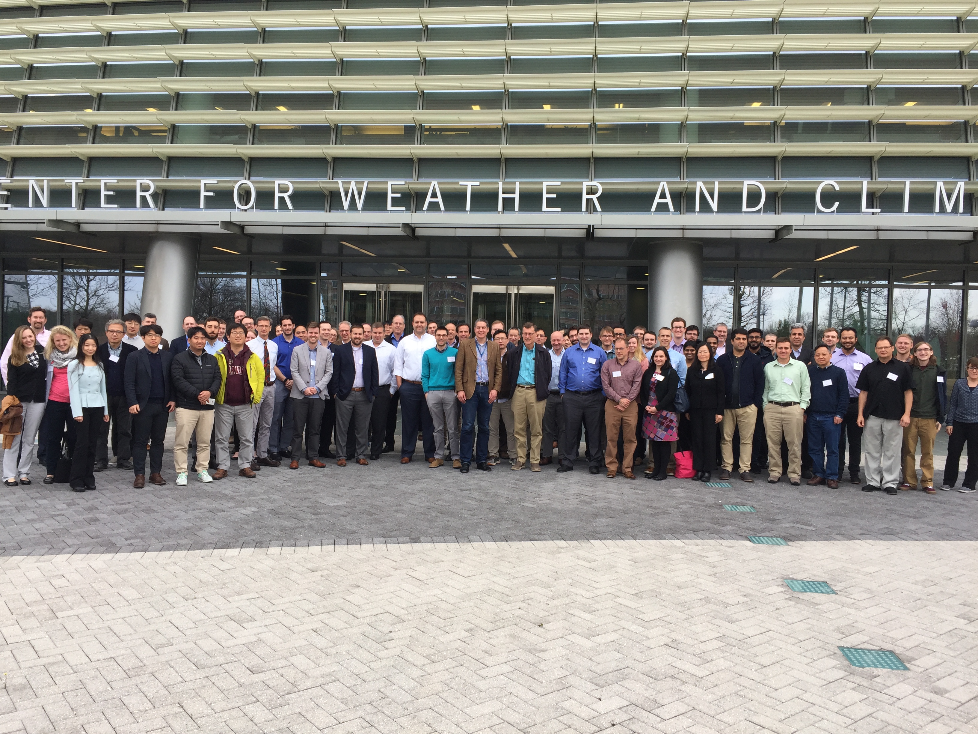
- 2020 Users Group Meeting Presentations
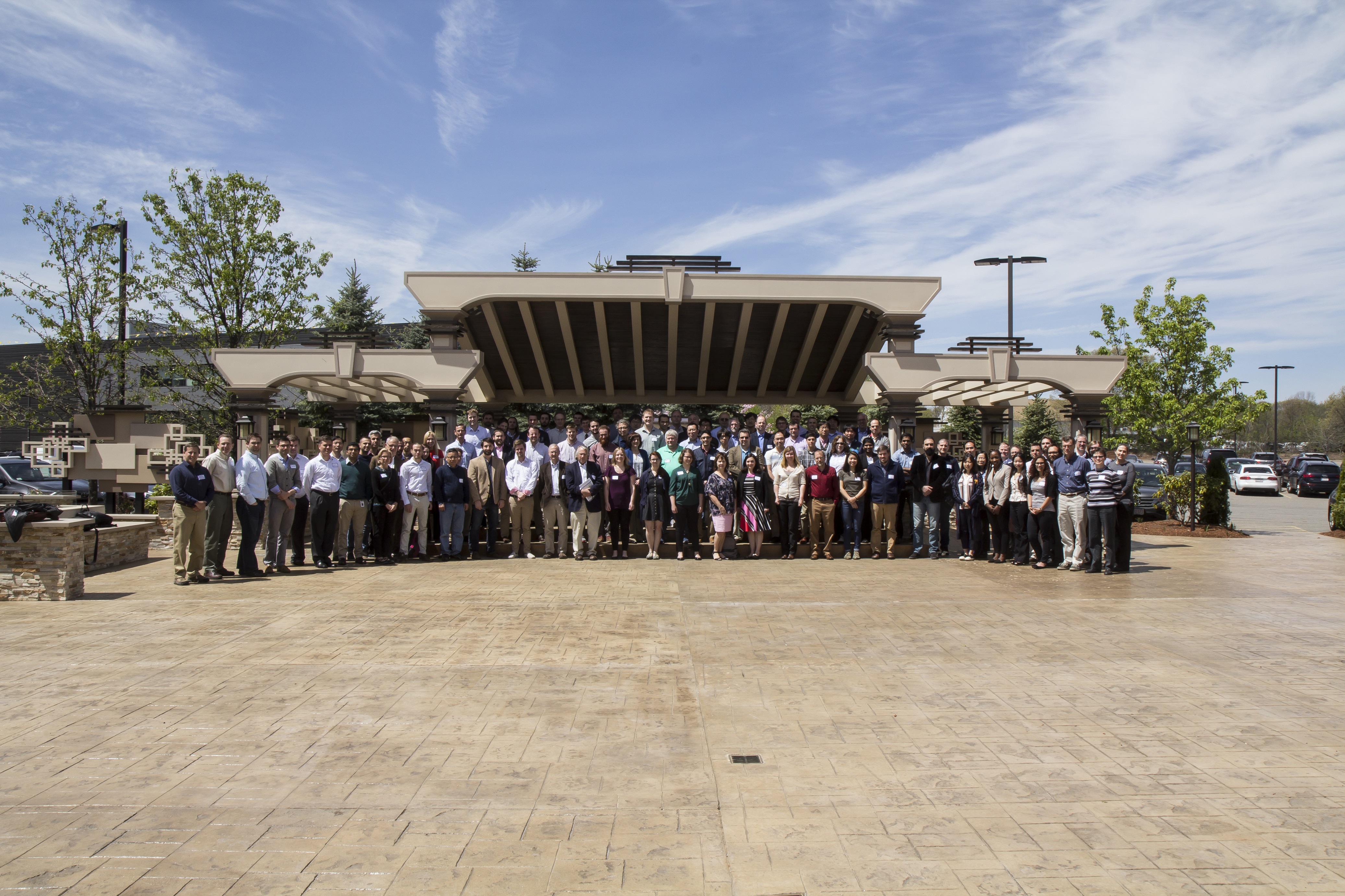
- 2019 ADCIRC Users Group Meeting
- 2019 Texas ADCIRC Week
- 2018 ADCIRC Week
- 2017 ADCIRC User Group Meeting and ADCIRC Boot Camp
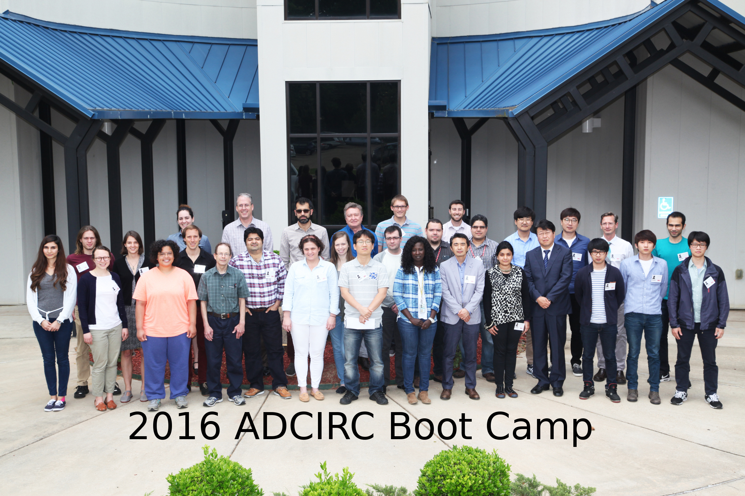
- 2016 ADCIRC User’s Group Meeting and ADCIRC Boot Camp
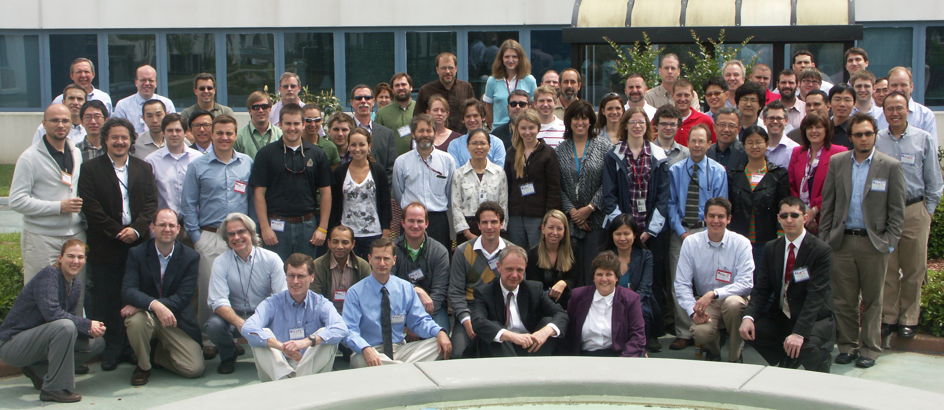
- 2015 ADCIRC User’s Group Meeting and ADCIRC Boot Camp
- 2014 ADCIRC Workshop and Bootcamp
- ADCIRC Workshop 2013 Final Agenda
- 2011 ADCIRC Workshop Press Release
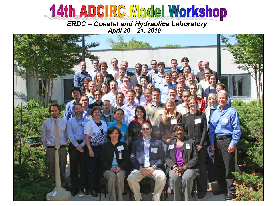
- 2010 ADCIRC Workshop Abstracts
- 2008 ADCIRC Workshop
- Hurricane Storm Surge Forecasts
- Example Hurricane Katrina Simulation
- Products
- ASGS